Posted by Wayne Parham [ 65.69.120.224 ] on May 28, 2005 at 14:24:17:
In Reply to: Re: ProFet Buildup - 1st Hour posted by Wayne Parham on May 25, 2005 at 19:43:20:
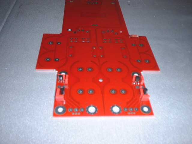
Now it's time to start on the power supply board. It is connected to the input boards so remove them all with a hacksaw. Smooth the edges with a file or sandpaper.
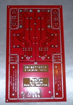 ProFet power supply board | 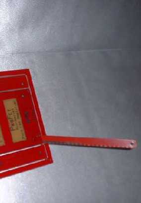 Using a hacksaw to separate the circuit boards | 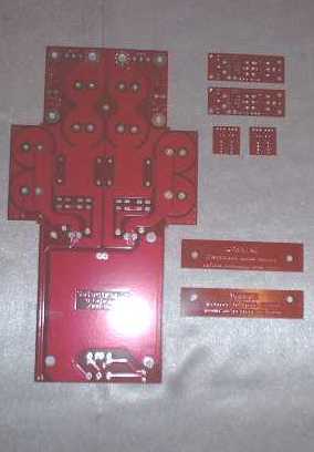 Individual boards |
You can identify parts and know where they should go from the component layout in the instructions:
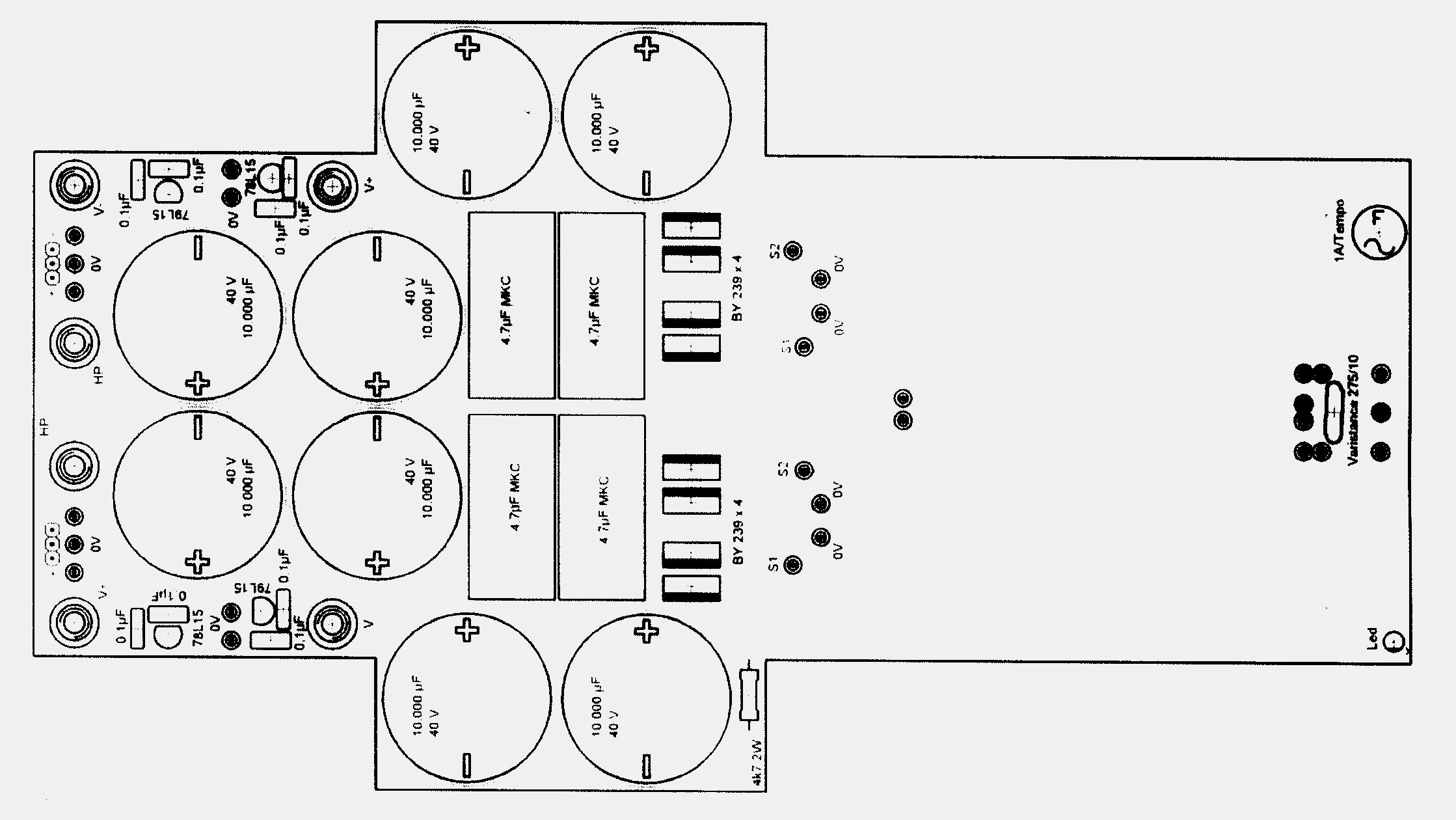
Solder the 7812 and 7912 regulators next, along with the 0.1μF capacitors and the 4.7kΩ, 2W resistor. Solder mask covers the mounting holes for the 4.7kΩ resistor, so remove it with a small knife or razor blade. It is easy to do, the solder mask is a layer of red laquer so just scratch some off the pads to expose the metal.
Now install the MOV, picofuse, (8) rectifiers and (4) 4.7μF capacitors:

Install the (8) 10,000μF capacitors and the two threaded spacers.
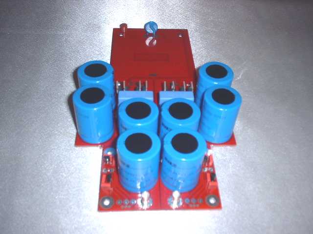
Cut a 4" length of 23 guage red wire and a 4" piece of 23 guage black wire. Solder the red wire to the long lead of the LED and the black wire to the short one. Twist the wires together and solder the red one into the "A" connection on the power supply board and the black wire to the "K" point.

Now clean each of the printed circuit boards, the power supply and both amp modules with flux remover and set them aside.
[ Selectronic Forum ] [ Help ]