Posted by Wayne Parham [ 64.216.179.187 ] on June 15, 2005 at 07:10:12:
In Reply to: Re: ProFet Buildup - 5th Hour posted by Wayne Parham on June 15, 2005 at 06:11:31:
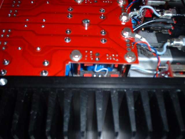
Now that the front and rear panels are mounted, the bottom panel can be removed for easier access to complete ProFet wiring. After removing the bottom panel, the chassis remains rigid because the heat sinks are mounted to the front and rear panels. But the circuit board assembly is now supported only by the power FET leads, so be careful to support the circuit board as you move the ProFet chassis around. Do not let the FET leads be stressed enough to bend and break.
First, connect the input wires. The longer white wire [In+] goes to the center hole and the shorter one goes to one of the the outside holes [In-]. Run the wires as shown here, physically close to one another. They are solid core wires, so they can be bent to shape.
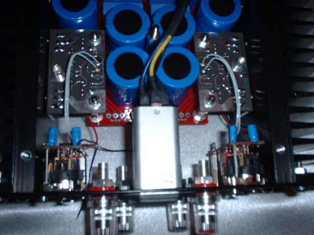
Next, braid the red, black and blue wires and connect them to the power supply board. As viewed from the bottom, the wires should be positioned in order, red, black and blue.
Cut two 2" pieces of 15 guage white wire and two 3 1/2" pieces. Solder silver spade lugs to one end of each, and solder the other end to the speaker connectors. The long ones go to the red connectors and the short ones to the black.
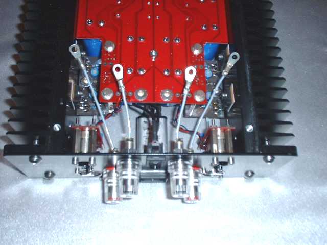
Using a silver bolt and washer, connect the speaker connector wires to the ProFet circuit boards. Click the photos below for a closer view:
 Black speaker connector hookup |  Red speaker connector hookup |
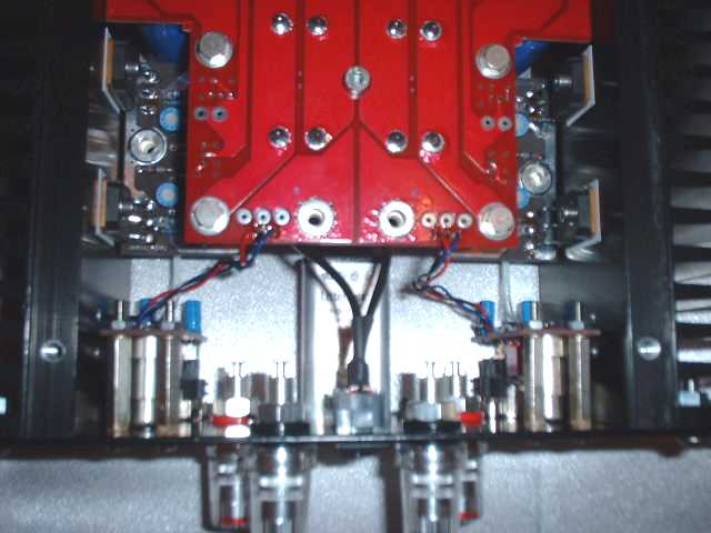
A short 22 guage wire must be connected between grounds on the power supply board and each output board:
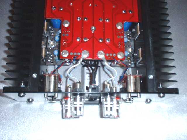
Now connect the AC power and you're ready for power on and final adjustments. With the transformer down and the circuit board up, the wires are in order, black, blue, yellow/green.
 AC input wires |  AC input to power supply |
Build the alignment tabs by soldering a 1Ω 1/4 watt resistor across the tab. One lead goes to one side and the other to the other.
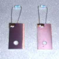
Remove the silvered bolts from the power supply board and slip the test tabs underneath, as shown below. Using a nylon screw, snug down the test tab. It doesn't have to be very tight, just snug enough to make connection.
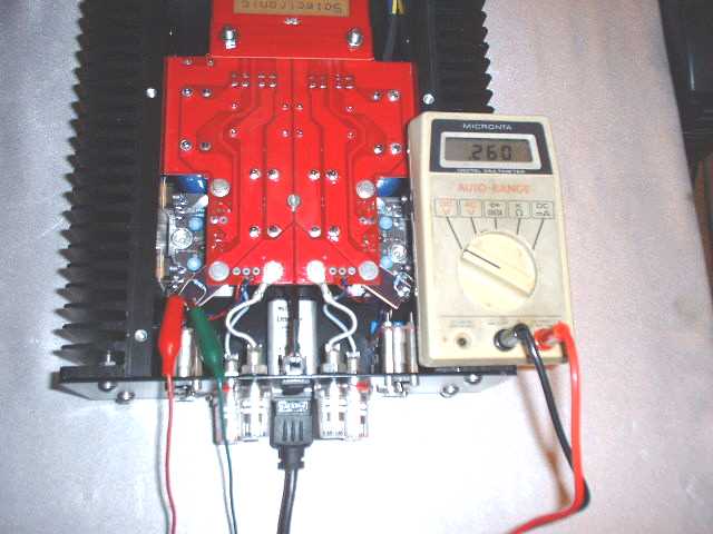
Now you're ready to power up. Set the trim pots all for center of scale. Check your wiring and if everything is OK, connect power and switch it on. You should see the blue LED glow and DC voltage across the speaker terminals should be less than 0.1v.
Adjust each trim pot so that the voltage across the test resistor is 0.260 volts and the voltage across the speaker terminals is 0.0v. The voltage across the test resistor is indirectly measuring quiescent current, which whould be 260mA, so since the resistor is 1Ω, 0.260v is ideal.
It's easiest to adjust these with two meters, or with a meter and an oscilloscope. I liked using the scope to watch DC offset across the speaker terminals, because I could switch between ground and input to make sure my offset was precisely 0.0v. Each pot will tend to move both DC offset and quiescent current. You want them to both be right.
After you've adjusted them, leave it on for 30 minutes and check it again. This will allow it to warm up. Do not side-step making the initial setting, because this ensures that the values aren't excessive. But the amp must warm up for a final reading, so make your second adjustment after the warmup period as precise as possible.
Remove the alignment tabs and nylon screws and store them. Reinstall the silver nuts and attach the top plate and bottom plate, instaling the bar feet on the bottom.
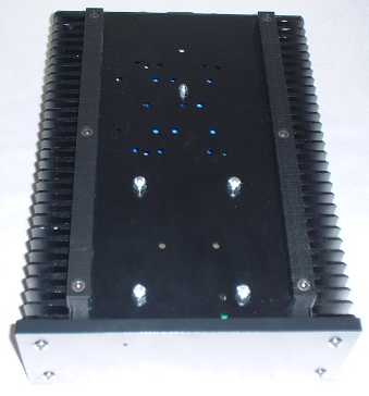
After that's done, hook up the preamp and connect the amp to your speakers and enjoy!
[ Selectronic Forum ] [ Help ]