Posted by Wayne Parham [ 65.69.120.224 ] on June 09, 2005 at 17:34:37:
In Reply to: Re: ProFet Buildup - 3rd Hour posted by Wayne Parham on June 03, 2005 at 17:12:44:
Now we'll mount the output boards. First thing is to add 1.25" threaded spacers on each one, like this:
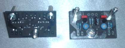
Mount the output boards on the power supply using a silver screw and washer:
Now lets prepare the power FETs for mounting on the heat sink. These are static sensitive devices, so take care when handling them.
First, cut pieces of conductive left over from parts you've already used. Make four pieces that can be used for each FET and set them on the anti-static bags. Grab a pair of scissors and touch the bag for a second or two. This will make sure that you, the scissors, bag and conductive foam pieces are all at the same voltage level.
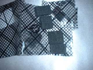
Cut open the bags and remove the transistors, pressing their leads into the conductive foam immediately. Leave some room for you to be able to get needle nose plyers onto the leads to bend them. Bend the leads as shown below:
 FETs in conductive foam | 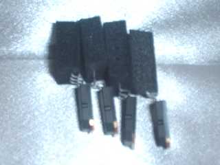 Leads bend to shape |
Find the self-adhesive transistor insulators and attach them to the heat sinks. Lay the heat sinks as shown below, and notice that the physical mounting of the transistors forms a mirror image of one another. When attaching the transistors, make sure that the 2SJ62 is on the left and the 2SK1058 is on the right on both heat sinks, viewed with pins down.
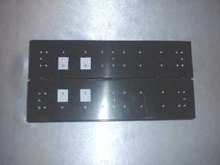 Heat sinks with insulators | 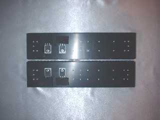 Transistors mounted |
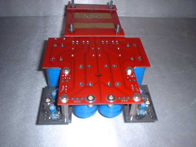
Screw together a 30mm and a 25mm standoff to form a 55mm one, which is about 2 3/16":
Mount it in the center of the power supply board, in between the group of four round 10,000uF capacitors:
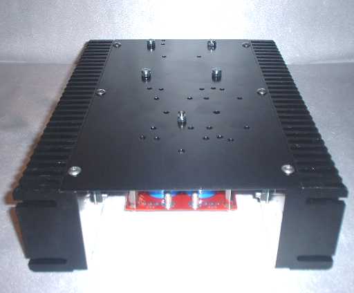
Mount the bottom plate with self-locking nuts.
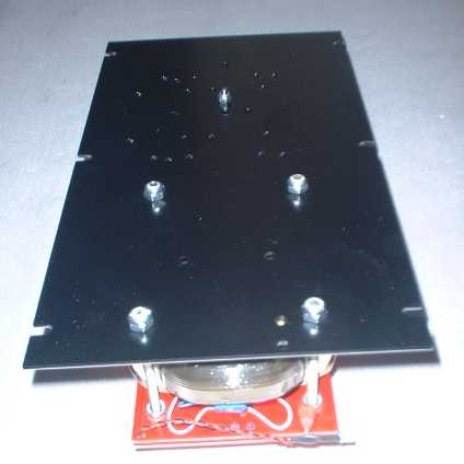 Bottom plate mounted |  Circuit side up |
Now lay the heat sinks beside the chassis, preparing to install them. Let everything touch for a second or two, so they all have the same voltage potential.
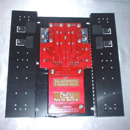
Remove the conductive foam from the transistors, and mount the heat sinks. Be careful to ensure each of the FET pins goes into the holes on the output boards and does not bent them. Use (6) button head screws to attach the bottom plate to the heat sinks and then solder the transistors in place.
 Heat sinks mounted |  FETs soldered in place |
[ Selectronic Forum ] [ Help ]