Posted by Wayne Parham [ 65.69.121.77 ] on February 09, 2005 at 12:52:39:
In Reply to: Re: Stoetkit Buildup - 3rd Hour posted by Wayne Parham on February 06, 2005 at 20:53:38:
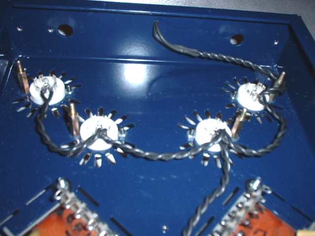
The tube heaters are all wired in parallel, off the 6.3VAC transformer output. Cut a pair of 6.5" wires and twist them together to connect the transformer to the first tube. Then cut three pairs of 4" wires for the rest of the tubes and twist 'em together. Wire to each tube socket pins 4 & 5, as shown below.

Tube filament wiring
Next, solder a 220 ohm, 1/4 watt resistor (red, red, brown) to one lead of the LED. It doesn't matter which one, because it is driven with AC. Then cut a pair of 5" wires and attach them to the LED and resistor. Put heat shrink tubing over the LED leads and resistor, as shown below. Then twist the wires, same as you did the filament wiring. These twisted pairs reduce AC noise inside the chassis.
 Heater resistors | 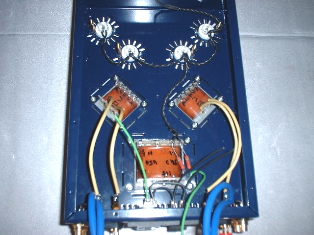 Heater wiring with LED and resistors |
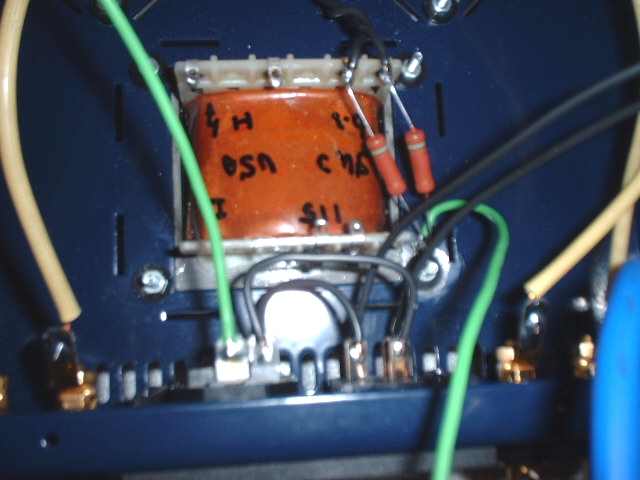
Now connect each of the tube anodes to the output transformer. The anode connection is pin 6. Notice that the wires from the left pair of tubes are crossed, when looking at the bottom of the chassis. This is to keep the phase right between channels.
[ FSAudio Forum ] [ Help ]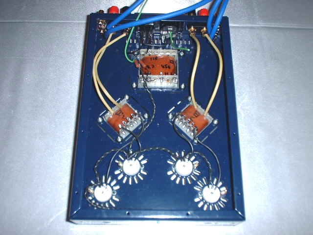
Tube anodes connected to output transformers
Connect the power switch to the power transformer and earth ground to chassis ground, as shown below. I had inserted the power switch into the chassis upside-down until this point; If you've done the same, release the spring-loaded clips with a flat screwdriver and carefully remove and re-install the power block. Or you can just wire it up as it is, and the power switch will just power on when flipped down.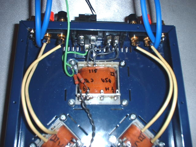
Power wiring
Next we'll build up the printed circuit board.