Posted by Wayne Parham [ 65.69.121.77 ] on February 10, 2005 at 20:35:12:
In Reply to: Re: Stoetkit Buildup - 5th Hour posted by Wayne Parham on February 09, 2005 at 23:04:27:
Now it's time to wire the printed circuit board. Using the black jacketed solid conductor wire, cut and solder in place several lengths of wires as shown below:
(6) 2" wires for J1A, J1B, J2A, J2B, J3A and J3B.
(4) 2½" wires for U1A, U2B, PA and PB
(2) 3" wires for U1B and U2A
(2) 9" wires for AC inputs, twist them together
(2) 8" wires for LSA and LSB
Also use a 6" piece of green wire for the chassis ground connection.
If you're like me, you will run out of black wire about the time you need to wire up the AC inputs. You'll be a foot or two too short. This is probably because the instructions used metric lengths and I rounded up. It was better for me to be a little long and trim back. So if you run out of wire, go out to the nearest electrical supply store and get a small spool of 18 guage solid conductor wire to complete the kit.
At this point, the amplifier is ready to run. The instructions describe a checkout procedure, and it's probably a good idea to follow it. But I'm always too impatient for that, prefering to use the "smoke test" instead. Following tradition, I inserted the tubes and powered it up. Here's what happened... No smoke, just sweeeeeet music. Diana Krall is peeling me a grape as I write this.
[ FSAudio Forum ] [ Help ]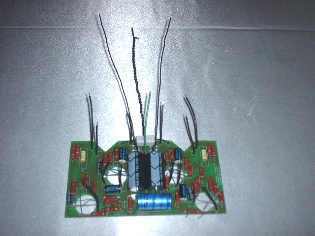
Printed circuit board with wires attached
Cut the green chassis ground wire in the center, forming two 3" lengths. Solder inline the 150 ohm resistor using heat shrink tubing to insulate the solder joints.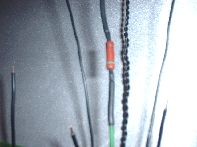
150 ohm ground resistor
Install the selector switch and volume potentiometer. Don't tighten them up yet, because you'll need some slack for installing the PCB and wiring them to it. I'd also suggest that if you soldered your ground strap right in the center of the potentiometer like I did, move it to the side or low on the back of the case. The printed circuit board comes rigt up to the back of the volume pot, so the wire will interfere if it's soldered to the center.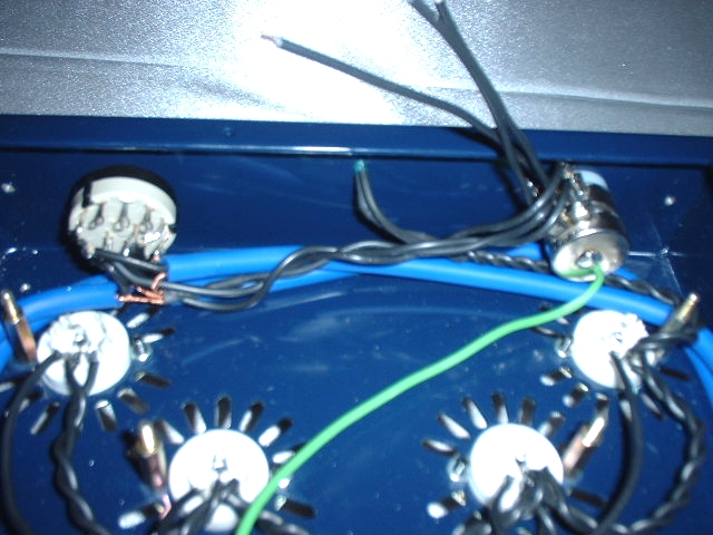
Volume potentiometer and selector switch installed
Give the printed circuit installation a "test run" to see how it is going to fit. You'll notice it's a very tight fit. You'll probably need to gently pry out on the mounting studs, moving the standoffs slightly outwards and bending the chassis mounts slightly. Make them aligned with the PCB mounting holes, so the board slides onto them easily. Also bend the leads on the selector switch and route the wires so that everything fits nicely without any pins touching each other or circuit traces near the edge of the circuit board. Solder the wires from the potentiometer to the PCB, being very careful not to break the delicate connection pads on the pot.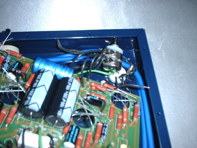
Inserting the printed circuit board
Slide the circuit board into the chassis at an angle, putting one side in first and then the other. Support the wires going to the potentiometers so that the pressure from bending doesn't break the potentiometer pads. The wires are much stronger and harder to bend than the potentiometer pads, so be careful with them. If one does pop free, tack it back in place with super glue. As long as the conductor doesn't break, that will work just fine.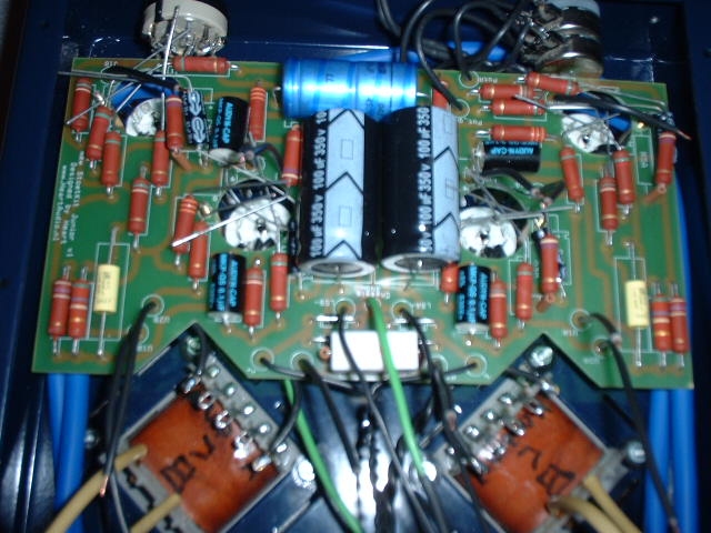
Printed circuit board in place
Now go through all the tubes, one by one, and connect up all the open wires. The silkscreen on the printed circuit shows where each lead should go. Also install the mounting nuts, using a dab of locktite on each one. On leads that come near each other or close to the mounting nuts, cover them with an insulator.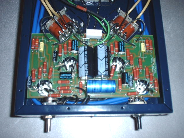
Printed circuit board installed, wired and ready to go.
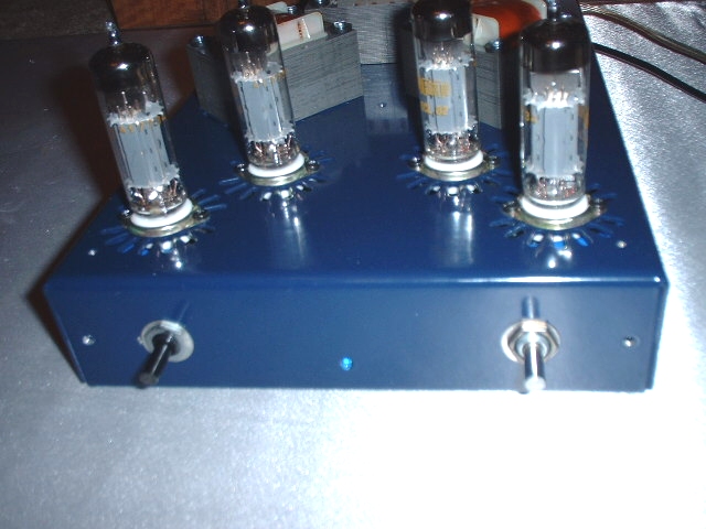
First power to the Stoetkit amp