Posted by Wayne Parham [ 65.69.121.77 ] on February 06, 2005 at 20:53:38:
In Reply to: Re: Stoetkit Buildup - 2nd Hour posted by Wayne Parham on February 05, 2005 at 14:12:34:
Moving right along, now it's time to wire up the connectors and the front panel. First, the switch should be set for dual-position and the switch and volume knobs should be cut to fit. The switch is made so that it can handle up to six positions. It's configurable to provide a stop at 2, 3, 4, 5 or 6.
Since the Stoetkit has only two inputs, many of the switch connector lugs aren't used and the stop should be set at the first stop. So remove the nut and lockwasher and pry the stop up with a thin screwdriver or utility knife. Position the stop so that it points at "2" and reinstall the lockwasher and nut.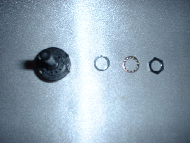
Input selector switch, with nut, washer and position stop removed
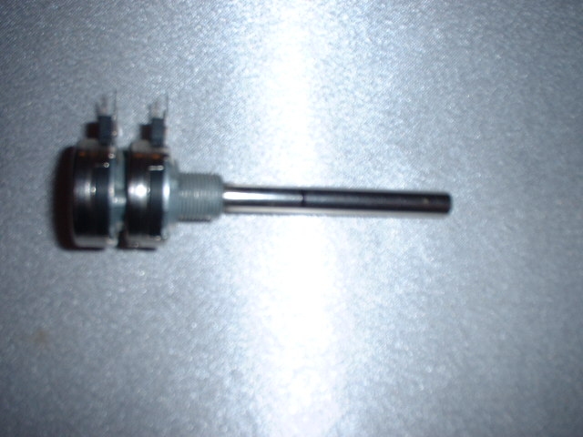 Stoetkit volume knob, uncut | 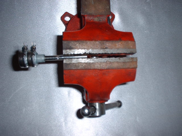 Cutting the knob, holding it with a vice |
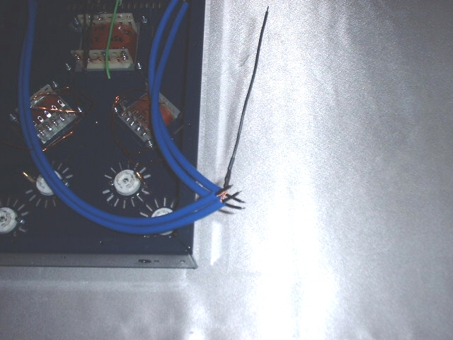
Now cut the signal coax cables to fit. They need to reach the selector switch, and they're probably a little long. Be careful not to cut too much, because once you've made your cut, you're committed. But they don't need much slack, and in fact, are better if there isn't much. Cut the coax cables to fit and then strip back 1/2" to expose the shield. Strip back 1/8" of the center conductor and tin it with your soldering iron. Twist each shield to form a single wire, and then connect the four together and solder them. Cut a 5" black wire and connect it to the shields. Then put the shrink tubing over the solder connection.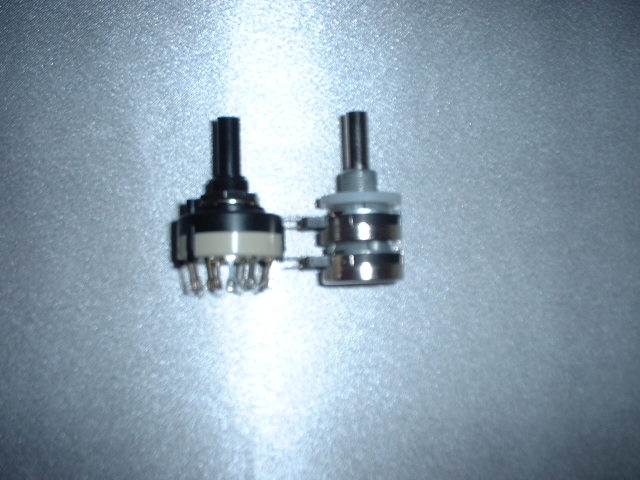
Selector switch and volume knobs cut to size
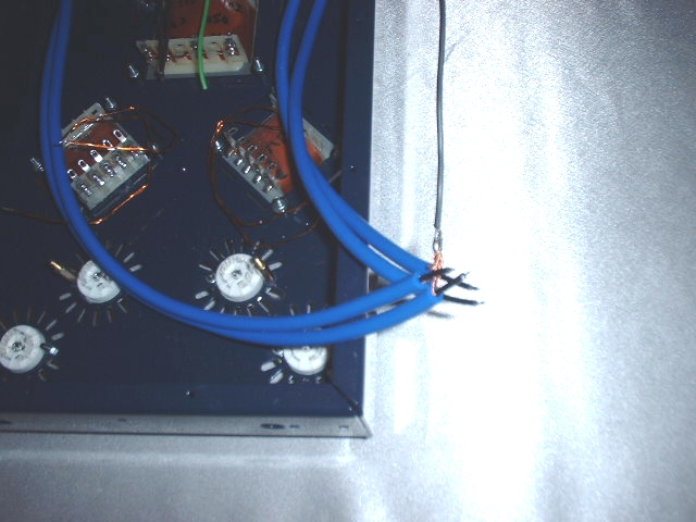
Shields soldered together with 5" wire
 Input selector switch and volume knob wired | 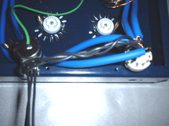 Closeup view |
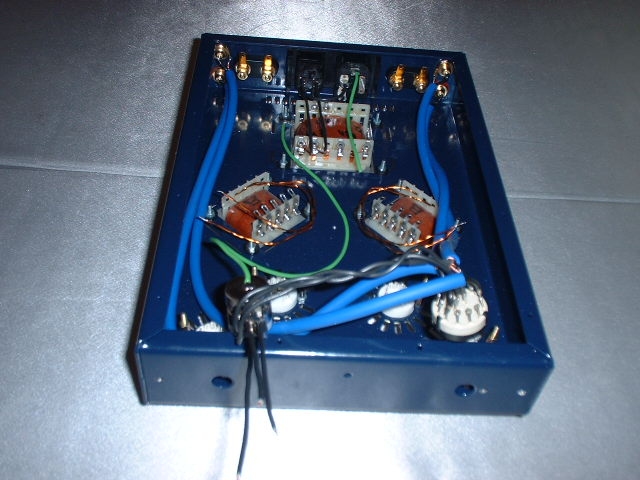
Now connect the output transformer to the output connectors. Notice from this view, the transformer on the left has wires physically crossed. That is important.
The instructions say to install the switch and volume knob now, but I would suggest against it. Wiring the tubes will be easier with them out of the way. And that's what we'll do next, wire up the filament heaters.
[ FSAudio Forum ] [ Help ]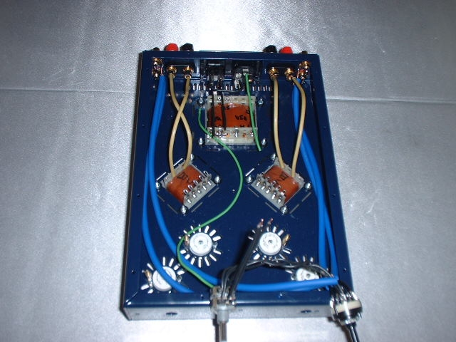
Output transformers wired to output connectors