|
Home » Sponsored » Pi Speakers » Build Thread: 2Pi Towers, 6Pi Corner horns (and possibly a sub and center) (Building some Pi Speakers)
| Re: Build Thread: 2Pi Towers, 6Pi Corner horns (and possibly a sub and center) [message #88178 is a reply to message #88057] |
Fri, 15 June 2018 00:54   |
 joshua43214
Messages: 35
Registered: October 2016
Location: USA
|
Baron |
|
|
This next part is difficult to describe in words. I will do my best, but I tend to fall into the pedantic style that science and math papers are written in, so please accept my apologies in advance if this post is a difficult read.
Many of you probably noticed the flare sides where rough cut as rectangles rather than as trapezoids. At first glance this might appear to be grossly wasteful of materials. It is, but the offcuts will be used later as bracing, mitigating some of the waste. The main reason they are cut as rectangles is so that the mouth and the throat are parallel to each other. This would be very difficult to accomplish otherwise. This ties back to my earlier post about constantly asking myself "how am I going to cut that, and how am I going to install that." Planning the cutting and assembly during the design stage is a huge benefit.
I will go ahead and describe part of the process for creating the CAD model for the flare in Fusion 360. My feeling is that most people who are willing to take on a speaker cabinet project will probably be also interested in using CAD. CAD has a bit of a learning curve. I dumped many thousands of dollars into CAD programs since the 90's, and I have found that Fusion 360 is the best all around tool for the work I do (and it is free).
I began by modeling a core that is the inside of the flare.
The image shows the core with the right side and the bottom. The base sketches for the core are visible inside the core.
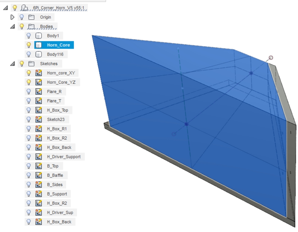
To model a side, I selected a side of the core as the reference plane, then just sketched a rectangle bigger than the core and extruded it to my material thickness. The adjacent faces of the core are then used as slicing planes to split the side, and the extra parts removed.
I found that I could not get the dimensions and angles in the plans provided by Wayne to work together. I am providing the link to the thread I started again for reference.
A pro-tip on modeling. When I drew the horn core, I began by making the base sketch for the core in the XY plane. I stopped the sketch without extruding it. While making sure the first sketch was visible, I started the base sketch for the YZ plane. By doing this, the first sketch will "auto-project" into the new sketch allowing one to constrain the intersections of the lines to be coincident. That way, when a change is made to one base drawing, it will force the other base drawing to adjust to it. Once both base drawings are completed, I returned to the first drawing and extruded it oversized. I then extruded the second drawing also oversized (ensure you are making a new body). The two 3D bodies are then used to split each other, and the offcuts removed leaving nothing but a single body.
One of the limits of Fusion 360 is that it is purely a 3D modeling program. 2D modeling is limited to base sketches that are extruded into 3D shapes. The software is meant for producing models that are made either by 3D printing or CNC machining. As such, the tools for producing shop drawings are limited since shop drawings are 2D.
When the 3D model is imported into the tool for generating shop drawings, all the parts are projected from the cardinal directions of top/side/etc. Parts that are not planar with one of the cardinal views will appear angled or foreshortened in the drawing space. Search YouTube for tutorials on creating custom views (it is very simple), and select the appropriate view when creating the shop drawing for the horn parts.
The angle that is needed for the saw blade is referenced to the bottom face of the flare, and is measured along the line perpendicular to the cut edge. There is no reliable way to create this reference in the shop drawing space.
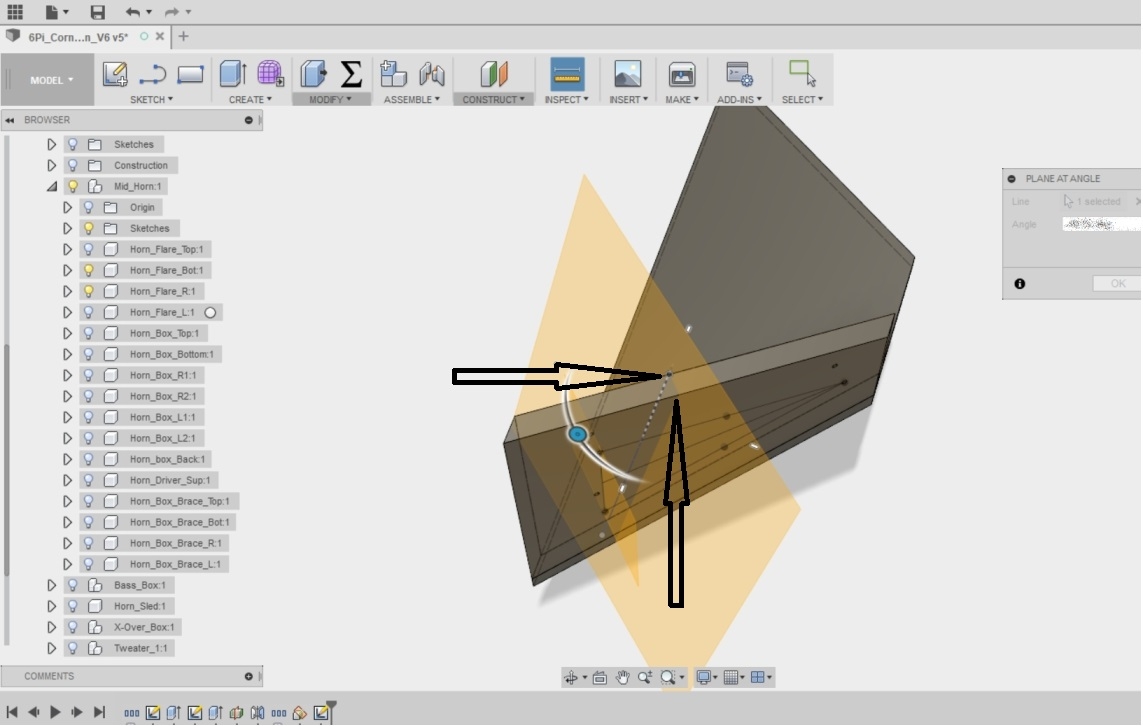
I found the simplest method to get this angle was to sketch a line on the inside face of the right side perpendicular to the cut, and use that line to create a new plane at a 90 degree angle. I then split the part with the plane, and copied the new part to a new model space, and used "undo" to remove all the edits (don't forget to break the link to the old model). The new part was exported to the drawing space as its own file, and my angle measurements taken from there. The angles for the mouth and throat can be taken from the main drawing.
Where to place the three holes for the pins will depend on your tooling. The digital read out on my mill resolves to 0.0001" (0.0024mm), so I just put them where they looked ok. All of the dimensions of the horn work together, so it is important to cut and measure as accurately as possible. Your dial indicator will scribe marks very accurately up to its capacity, but making marks 12" or so inches from the edge are problematic.
Here is my suggestion for making the layout. This assumes you acquired a machinist combination square that does not suck. It is a really good idea (like really good) to go through all the horn parts and mark all 4 edges on both faces right/left/top/bottom/inside/outside, and to group them as horn #1 and #2.
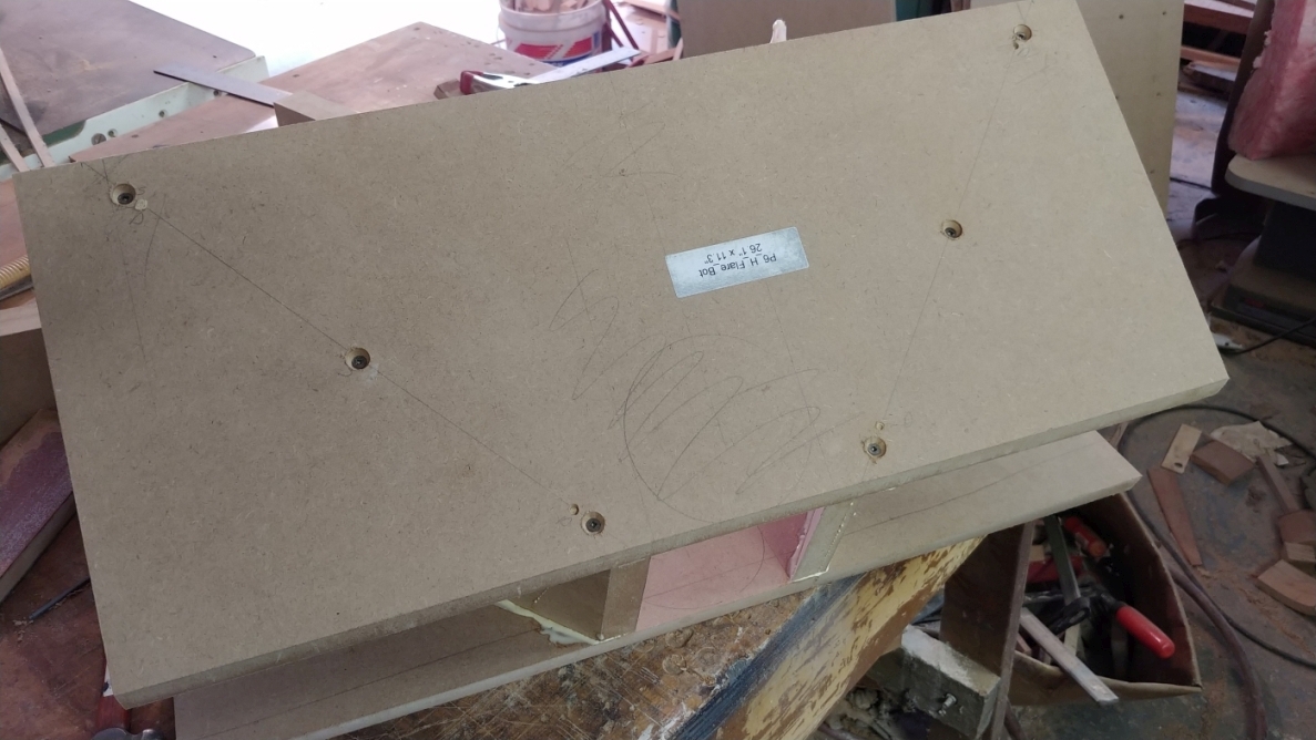
Cut the mouth and throat angles, cut the parts as close as you can measure. Reading glasses make nice magnifiers when using precision rulers (I think I forgot to include a 24" machinist scale in the tooling list). Strike a line perpendicular to the mouth bisecting the part. The 12" scale that comes with the combination square can be used to place the hole closest to the throat. Use a dial caliper to scribe a line parallel to the mouth that passes through point A in the pic below. Set the trammel to 10" (check and double check this, get fussy). Strike an arc across the part with the point near the throat and the center. Use the dial caliper to scribe the points closest to the mouth (distance H). Those of you without a flag on the Moon will have to use whatever metric dimensions are standard on tools in your location.
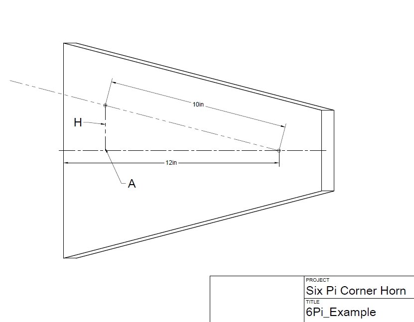
Lightly center punch, and drill with a drill press. I like to use a center point in the drill press to locate the part, then swap in the drill bit. It takes a bit of extra time to swap out the drill before each hole, but there is only 12 holes to drill. Following any method similar to this reduces you to making one questionable measurement (the 10 distance for the trammel), but this distance is only measured 1 time. Even if it is off a bit, the horns will be identical to each other.
An argument for cutting the mouth and throat angle first, as opposed to leaving them square and trimming them later: If the mouth and throat are left square, it will be more difficult to align the top to the sides. Trimming later requires sanding a substantial amount of MDF away, and it will be difficult to ensure the entire face of the flare is flat because of its size. Cutting the angles first does require an extra machine set up, and leaves you referencing from a sharp and fragile edge, but saves time and increases accuracy at the same time.
Use a precision protractor to set the table saw blade. It is vitally important that the protractor be perpendicular to the blade when the measurement is made. I use the miter gage to hold it square. Put a light at the back of the saw, and see how much light leaks between the blade and the protractor. Slide the protractor over, and then back to the blade to double check. This is a point to get fussy over.
At this point, you should have horn sides that are cut to size on all 4 edges, and tops/bottoms that are cut only at the appropriate angle at the mouth and throat.
The flare top and bottom are identical, so I will only talk about the top from this point forward.
Using a framing square (you did Google up how to square a square, didn't you?), bisect the inside face of the top using the mouth as the reference, and taking care the square is referenced on the edge and not on the bevel. Cut some scrap exactly 4.5" as spacers for the horn throat. Use a compass to draw a 4.5" circle near the throat on the bisecting line. Very carefully measure out from the bisecting line the distance to the outside edge of the side, and set the trammel to this distance. Use the trammel to repeat these marks to all the tops and bottoms. Doing this will ensure the horns are identical even if your measurement is slightly off.
Mark a line on the outside of the top that will be directly over the center line of the sides.
Clamp the spacer using the compass circle to get it aligned. If you took your time and where very careful, the throat will be laid out exactly over the center of the mouth.
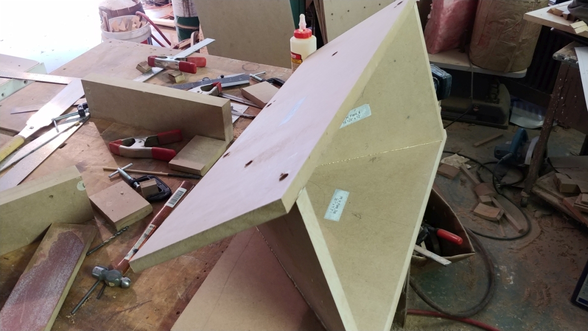
Dry assemble the horn. It took some playing around to figure out how to hold everything together.
Get the whole horn lined up. With some patience, you will find that it will come together properly. Carefully drill a hole for a 1/4" (5mm) dowel near the throat. Trim a piece of dowel, sand it enough that it can be lightly tapped in with a mallet, and then re-align everything (it will have shifted when you drilled). repeat until you have a pair of dowels on each glue joint (8 total). Plan to spend some quality time doing this.
Line the drill up carefully, there is a strong optical illusion that will lead you astray.
Once all the dowels are in, drill holes for #10 screw threads. Dismantle the horn and drill out the screw holes in the top to clear the threads. Counter sink the holes on the inside of the joint.
Dry fit the parts again using screws and dowels. Tighten the screws just enough to pull it together. inspect closely for gaps or poor fitting. If all went well, you should see no issues. If the joints are not well fitting, you will have to clean them up by hand with a sanding block.
Apply glue and screw it all together. Measure corner to corner at the mouth to make sure the assembly is square. Yellow glue is a good choice with this. If the glue joint is not tight, use epoxy. Do not use polyurethane glue on a poor fitting joint. Polyurethane glues are very weak on joints with gaps, and they are highly porous because of how the expand.
Make sure you remove the 4.5" spacer before it gets glued in place. After about 40 minutes, clean up the glue with a chisel.
Remove the screws and trim the top and bottom flush with a handsaw.
Congratulations, you just built something awesome.
Many years ago I subscribed to Fine Woodworking Magazine (when it was still a mag for professionals). Every month they would feature a "Master Class" where some master craftsman would make something awesome. One month, the feature was about making a feed trough. Is it essentially the same thing as this horn flare only about 3 times the size. Everyone was amazed at how difficult the project was. It turns out that there was a class of woodworkers similar to coopers who did this type of work. It is difficult enough that specialists existed at one time for doing it.
Up Next: The Horn box
|
|
|
|
 |
|
Build Thread: 2Pi Towers, 6Pi Corner horns (and possibly a sub and center)
|
|
|
Re: Build Thread: 2Pi Towers, 6Pi Corner horns (and possibly a sub and center)
|
|
|
Re: Build Thread: 2Pi Towers, 6Pi Corner horns (and possibly a sub and center)
|
|
|
Re: Build Thread: 2Pi Towers, 6Pi Corner horns (and possibly a sub and center)
|
|
|
Re: Build Thread: 2Pi Towers, 6Pi Corner horns (and possibly a sub and center)
|
|
|
Re: Build Thread: 2Pi Towers, 6Pi Corner horns (and possibly a sub and center)
|
|
|
Re: Build Thread: 2Pi Towers, 6Pi Corner horns (and possibly a sub and center)
|
|
|
Re: Build Thread: 2Pi Towers, 6Pi Corner horns (and possibly a sub and center)
|
|
|
Re: Build Thread: 2Pi Towers, 6Pi Corner horns (and possibly a sub and center)
|
|
|
Re: Build Thread: 2Pi Towers, 6Pi Corner horns (and possibly a sub and center)
|
|
|
Re: Build Thread: 2Pi Towers, 6Pi Corner horns (and possibly a sub and center)
|
|
|
Re: Build Thread: 2Pi Towers, 6Pi Corner horns (and possibly a sub and center)
|
|
|
Re: Build Thread: 2Pi Towers, 6Pi Corner horns (and possibly a sub and center)
|
|
|
Re: Build Thread: 2Pi Towers, 6Pi Corner horns (and possibly a sub and center)
|
|
|
Re: Build Thread: 2Pi Towers, 6Pi Corner horns (and possibly a sub and center)
|
|
|
Re: Build Thread: 2Pi Towers, 6Pi Corner horns (and possibly a sub and center)
|
|
|
Re: Build Thread: 2Pi Towers, 6Pi Corner horns (and possibly a sub and center)
|
|
|
Re: Build Thread: 2Pi Towers, 6Pi Corner horns (and possibly a sub and center)
|
|
|
Re: Build Thread: 2Pi Towers, 6Pi Corner horns (and possibly a sub and center)
|
|
|
Re: Build Thread: 2Pi Towers, 6Pi Corner horns (and possibly a sub and center)
|
|
|
Re: Build Thread: 2Pi Towers, 6Pi Corner horns (and possibly a sub and center)
|
|
|
Re: Build Thread: 2Pi Towers, 6Pi Corner horns (and possibly a sub and center)
|
|
|
Re: Build Thread: 2Pi Towers, 6Pi Corner horns (and possibly a sub and center)
|
|
|
Re: Build Thread: 2Pi Towers, 6Pi Corner horns (and possibly a sub and center)
|
|
|
Re: Build Thread: 2Pi Towers, 6Pi Corner horns (and possibly a sub and center)
|
|
|
Re: Build Thread: 2Pi Towers, 6Pi Corner horns (and possibly a sub and center)
|
|
|
Re: Build Thread: 2Pi Towers, 6Pi Corner horns (and possibly a sub and center)
|
Goto Forum:
Current Time: Sun Apr 28 05:38:07 CDT 2024
|


 Posting Rules
 Members
 Search
 Help
Help Register
 Login
Login Get a T-Shirt!


")

