|
Home » Sponsored » Pi Speakers » 4 Pi revisited first impression
| Re: 4 Pi revisited first impression [message #74647 is a reply to message #74642] |
Thu, 29 November 2012 10:10   |
 |
 Wayne Parham
Messages: 18688
Registered: January 2001
|
Illuminati (33rd Degree) |
|
|
Thanks for posting here. As I read your post, I remembered the days about ten or twelve years ago when many people on this forum were "doing their own thing" like this, maybe as many as half of the builders deviating from the plans in one way or the other. It's refreshing to see that here again.
I tell so many people not to deviate from the plans if they don't have measurement equipment and time. And I think that's good advice, because there are a lot of "weekend warriors" that probably can't take the time to test and optimize a design if they make changes. But with modeling tools and measurement equipment, you can certainly do something like this and do it well. There are a lot of ways to get it "right" - not just one. Of course, there are a lot more ways to get it wrong too, but the point is if you have the time and know-how to dial it in, you can get there too.
| Arthur C wrote on Thu, 29 November 2012 07:49 | The horn chosen is the RCF H100 very popular in the DIY world and the woofer chosen is the Eminence Kappa 15A.
|
At one time, there were a LOT of people here running the Kappa 15. I had considered using it too, because it is very similar to the Omega 15. But in the end, that's why I didn't use it - There was no need to offer something so similar as an option.
I'd say the H100 is pretty much the same as the older H290 horn with twice the vertical beamwidth. To be honest, I'd prefer a little less vertical, but other than that, it appears to be a good horn.
| Arthur C wrote on Thu, 29 November 2012 07:49 | For the woofer, I have substituted a 25 microFarad capacitor and a 6.5 ohm resistor instead of 20 microFarad and 8 ohms (C5 and R3).
|
That will give you a smidge less midwoofer peaking in the ~1200Hz region. But I'd consider it pretty much a non-change because Zobels are fairly wide tolerance networks. You can see this in the last couple of pages in my "Crossover Electronics 101" document. Because of the relaxed requirements of the Zobel values, I tend to pick components that are readily available with high-power dissipation capacity since Zobels take a beating.
| Arthur C wrote on Thu, 29 November 2012 07:49 | For the couple B&C DE 250 and RCF H100, I have operated some little modification in order to take into account that the frequency response of the H100 less attenuates the high frequencies as the H290.
Thus, I have substituted the 0.47 microFarad capacitor with a 0.33 microFarad (C1).
Considering that the RCF H100 horn creates a little peak around 2kHz, I have used a 4.8 microFarad (3.3+0.47) capacitor instead of the recommended 6.8 microFarad in Wayne's schematic (C2).
|
I realize it would require a baffle change, but consider trying our H290C waveguide sometime. Shipping is not expensive, so many of our overseas customers buy this part alone (or this and a crossover) and source their drivers locally.
The H290C waveguide is as smooth as I've seen any horn be, and it provide a great coverage pattern with very little high-order modes. Its profile is oblate spheroidal, and its length/area ratio gives it good beamwidth and best-of-class smoothness of response.
| Arthur C wrote on Thu, 29 November 2012 07:49 | Concerning the size of the enclosure, some very slight modifications have been also done but with the same internal volume as the volume mentioned in Wayne's plan. Concerning the port, some modifications have been introduced. I have used a 10cm diameter port with 14 cm length. Frequency tuned around 35 Hz.
|
Be sure to perform acoustic measurements to verify that you have not introduced midrange ripple between 100Hz and 200Hz. Standing waves inside the enclosure can cause midrange anomalies if the port falls on a pressure node.
| Arthur C wrote on Thu, 29 November 2012 07:49 | I just wondering about one point, in Wayne's schematic C4 is 10 micro. In accordance to my calculation it should be 20 micro. I haven't tried this substitution. Is someone able to explain me ?
|
It measures better. When C4 is 20uF, the forward lobe is about 5° too low. The bottom null is around 30° below the forward centerline and the top null is about 20° above it.
By changing to a 10uF value C4, the nulls are more evenly spaced, +/- 25°. Depending on what you call the "centerline" - center of the box or midpoint between woofer and tweeter centerlines - it can even be considered to be slightly upward now, which I think is preferable to pointing slightly downward.
The bottom line is substituting 10uF for 20uF in C4 creates a subtle shift in the position of the forward lobe, slight but I think worthwhile.
As an aside, this is one of those tiny details you'll never see with modeling tools. I suppose one day, computer simulations might get to a point where they would give this level of visibility - They're clearly improving compared to what was available in decades past. But progress is slow. It's hard to justify the R&D expense when there is such a small market for loudspeaker simulation tools, so it is almost exclusively in the realm of hobbyists. That's why what is out there is either too oversimplified to give any real visibility or too specialized on one aspect or another, incapable of modeling the loudspeaker as a complete system. And in either case, you really have to verify the mathematical models in the simulation programs closely before you trust them because there generally is no Q/A team for a hobbyist project.
| Arthur C wrote on Thu, 29 November 2012 07:49 | I was wondering about the frequency response in the low frequencies. Even if in the specifications the -3db is around 50/60Hz, there is no lack of bass. A 15' woofer reproduces low frequencies much more better than 6 or 8' woofer commonly installed in hifi speaker. You have real bass with power, definition and impact and less compression than 6 or 8' woofer.
|
Yes, the bass response sounds subjectively much more full and powerful than the measurements indicate. I'm completely satisfied listening to speakers like these without subs, especially in large rooms or outdoors where room modes aren't a problem. But then again, the deepest bass really isn't there and you'll notice it when you add subs. This, combined with the fact that properly positioned subs will smooth room modes in the bass and even self-interferece notches in the lower midrange, makes me inclined to always run flanking subs with these speakers, and sometimes one or two more distant subs in rooms where lower frequency modes are noticeable.
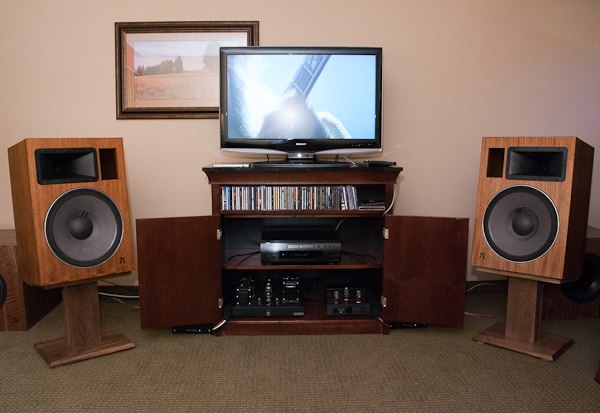 four π speakers flanked with three π subs
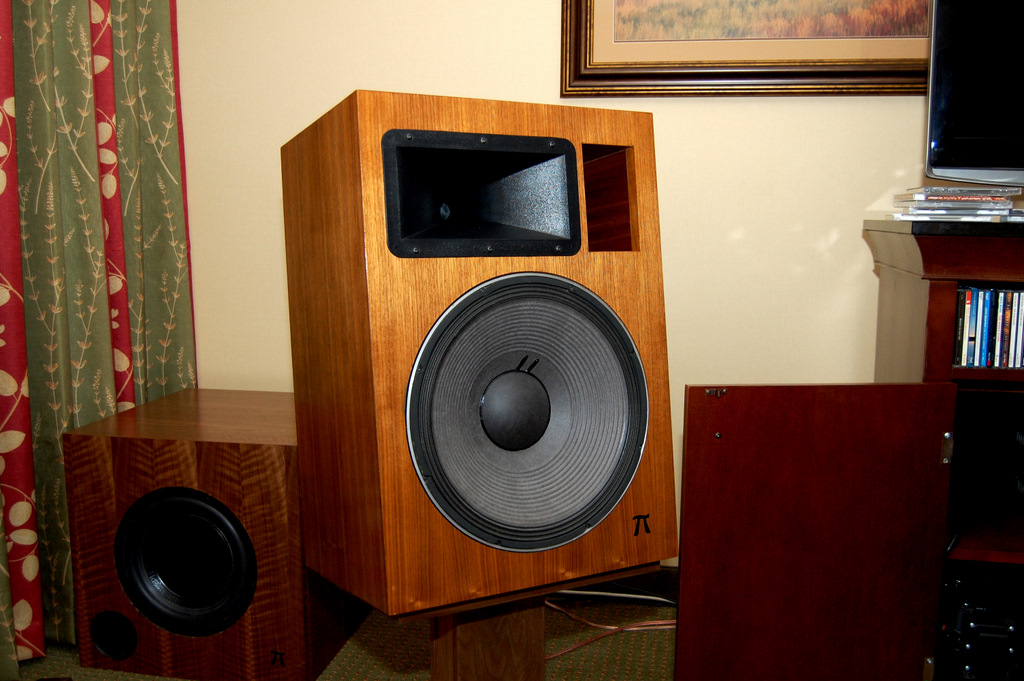 Closeup of left speaker and its flanking sub
|
|
|
|
Current Time: Mon May 13 15:49:06 CDT 2024
|


 Posting Rules
 Members
 Search
 Help
Help Register
 Login
Login Get a T-Shirt!


")

