|
Home » Sponsored » Pi Speakers » H290C Horn/Waveguide (Upgrade for the obsolete Eminence H290)
| Re: H290C Horn/Waveguide [message #76563 is a reply to message #76448] |
Tue, 30 April 2013 13:15   |
 |
 Wayne Parham
Messages: 18678
Registered: January 2001
|
Illuminati (33rd Degree) |
|
|
In the chart above, you can only really see evidence of waistbanding in the 12dB strata. As I said, I think this is largely caused by the renderer, which seems to fill the strata with any values less than the stratification level without any interpolation or curve fiting. The waistbanding level is less than 6dB lower than midband, so it just doesn't show up.
Also, the scale is logarithmic which reduces the size of the waistbanding region, making it more difficult to see.
To help better illustrate waistbanding in the H290C, we can change the scale of the sonogram to logarithmic. That stretches the area where waistbanding occurs. See the charts below:
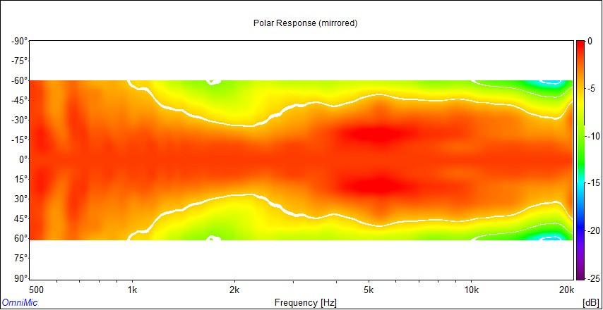 H290C horizontal sonogram using logarithmic scale
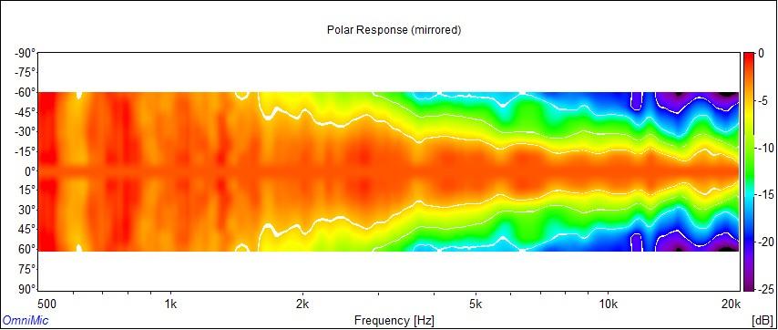 H290C vertical sonogram using logarithmic scale
These are sonograms made for the H290C using a different renderer and plotted on a logarithmic scale. The measurements were made in a different environment too, so there are slight differences in the data but it shows general agreement with the other measurements. The biggest difference is in the rendering and the logarithmic scale, where here we can sort of put the waistbanding region under a magnifying glass.
See the color scale at the right side of each chart. This legend shows us a color gradient mapped to SPL.
You will notice that horizontal waistbanding centers around 1.8kHz, and its effects are about 2dB reduction of sound at 45° compared to the midband levels. That's what waistbanding does. It reduces output slightly at the edge of the beam.
As a sanity check, we can calculate waveguide beamwidth using formulas from Keele's paper, "What's so Sacred About Exponential Horns?"
Pattern Control Lower Limit = (106 / Mouth Width * Wall Angle)
Waistbanding Frequency = 1.5 * Pattern Control Lower Limit
Waistbanding Pinch Angle = 2 * Pattern Control Lower Limit / 3
Therefore, the H290C has properties somewhere in this range:
106 / 11" * 85° = 1070Hz (lower limit of pattern control)
1070 * 1.5 = 1.6kHz (waistbanding center frequency)
2 * 85 / 3 = 60° (waistbanding minimum beamwidth angle)
Earlier measurements showed waistbanding centered around 1.4kHz. The measurements above show it to be centered around 1.8kHz. Both are reasonable, given the different environments they were taken in, and both match our expectations of 1.6kHz fairly well. One is a little higher than predicted, the other a little lower, but both are within 10% of what Keele's formula predicts. In each case, you can look at the charts and see less output at the waistbanding minimum frequency than midband. It falls a couple decibels more in the waistbanding region than it does at higher frequencies.
In my opinion, the 2dB loss at 45° from waistbanding is acceptable, especially since the woofer and tweeter are blended in the crossover region anyway. Even if they weren't, as is increasingly the case with the larger midwoofers, what we're really talking about here is a slight decrease in output at wide off-axis angles. By slight, I mean practically nothing. The 2dB drop at wide off-axis angles is completely inaudible.
Waistbanding is more damaging in a prosound implementation. In that application, the problem is not so much the slight squeeze of the pattern as it is the secondary lobe, which affects arrayability. But in this case, we're not concerned with that. A two-way or three-way speaker using an H290C waveguide has no other sources with radiation at angles that would create an interference pattern with the secondary lobe.
The thrust of the H290C design approach was to shift all anomalous behavior as low in frequency as possible. The idea was to sacrifice a little bit of waistbanding at the bottom end for smoothness from midband up. Crossover occurs between 1.2kHz and 1.8kHz, with that region blending woofer and tweeter output together. So by optimizing tweeter performance above that point, we are optimizing where tweeter fidelity is needed the most.
What we gain in the trade is a flare profile that keeps the wavefront propogation perfectly perpendicular to the wall angle all the way through the horn. We also gain better acoustic loading, which is important in a conical horn or waveguide, because they are characteristically weak in this regard. They need all the help they can get. Improved acoustic loading provides smoother response, greater efficiency and lower distortion.
We haven't talked much about distortion, but consider that for a moment. By increasing efficiency, you reduce drive requirements. So not only does the improved acoustic load reduce diaphragm excursion, but it also increases efficiency, which reduces the drive requirements as well. This, in turn, reduces excursion even further.
A 3dB increase in sensitivity means 1/2 power is required to obtain the same SPL. So the distortion reduction is improved by two mechanisms, one being the reduced excursion from loading, the other being reduced excursion from reduced drive signal. The improvements from horn loading are cumulative where distortion reduction is concerned. This is true in all horns, basshorns and midhorns, but even more true in compression drivers, because they are designed for use where loading is good. They do not have much excursion capability, because they're designed to be used on a horn, not on a baffle.
|
|
|
|
 |
|
H290C Horn/Waveguide
By: santos on Tue, 27 March 2012 03:48 |
|
|
Re: H290C Horn/Waveguide
|
|
|
Re: H290C Horn/Waveguide
By: Maxjr on Thu, 29 March 2012 13:26 |
|
|
Re: H290C Horn/Waveguide
|
|
|
Re: H290C Horn/Waveguide
|
|
|
Re: H290C Horn/Waveguide
|
|
|
Re: H290C Horn/Waveguide
By: Maxjr on Thu, 17 May 2012 16:37 |
|
|
Re: H290C Horn/Waveguide
|
|
|
Re: H290C Horn/Waveguide
|
|
|
Re: H290C Horn/Waveguide
|
|
|
Re: H290C Horn/Waveguide
|
|
|
Re: H290C Horn/Waveguide
|
|
|
Re: H290C Horn/Waveguide
By: zheka on Fri, 27 July 2012 19:58 |
|
|
Re: H290C Horn/Waveguide
|
|
|
Re: H290C Horn/Waveguide
By: zheka on Sun, 29 July 2012 08:32 |
|
|
Re: H290C Horn/Waveguide
|
|
|
Re: H290C Horn/Waveguide
By: mantha3 on Tue, 31 July 2012 11:17 |
|
|
Re: H290C Horn/Waveguide
|
|
|
Re: H290C Horn/Waveguide
By: mantha3 on Tue, 31 July 2012 14:28 |
|
|
Re: H290C Horn/Waveguide
By: blvdre on Tue, 31 July 2012 15:35 |
|
|
Re: H290C Horn/Waveguide
|
|
|
Re: H290C Horn/Waveguide
|
|
|
Re: H290C Horn/Waveguide
By: Maxjr on Thu, 16 August 2012 07:42 |
|
|
Re: H290C Horn/Waveguide
|
|
|
Re: H290C Horn/Waveguide
By: Maxjr on Thu, 16 August 2012 14:11 |
|
|
Re: H290C Horn/Waveguide
By: gofar99 on Sat, 18 August 2012 14:35 |
|
|
Re: H290C Horn/Waveguide
By: Maxjr on Wed, 22 August 2012 22:48 |
|
|
Re: H290C Horn/Waveguide
|
|
|
Re: H290C Horn/Waveguide
|
|
|
Re: H290C Horn/Waveguide
|
|
|
Re: H290C Horn/Waveguide
|
|
|
Re: H290C Horn/Waveguide
|
|
|
Re: H290C Horn/Waveguide
|
|
|
Re: H290C Horn/Waveguide
|
|
|
Re: H290C Horn/Waveguide
|
|
|
Re: H290C Horn/Waveguide
|
|
|
Re: H290C Horn/Waveguide
By: rkeman on Thu, 21 March 2013 14:20 |
|
|
Re: H290C Horn/Waveguide
|
|
|
Re: H290C Horn/Waveguide
|
|
|
Re: H290C Horn/Waveguide
By: zheka on Tue, 23 April 2013 09:59 |
|
|
Re: H290C Horn/Waveguide
|
|
|
Re: H290C Horn/Waveguide
By: zheka on Tue, 23 April 2013 11:03 |
|
|
Re: H290C Horn/Waveguide
|
|
|
Re: H290C Horn/Waveguide
By: zheka on Tue, 23 April 2013 11:20 |
|
|
Re: H290C Horn/Waveguide
|
|
|
Re: H290C Horn/Waveguide
|
|
|
Re: H290C Horn/Waveguide
|
|
|
Re: H290C Horn/Waveguide - closest equiv. in 1.5" or 2"?
By: tubino on Thu, 17 September 2020 14:41 |
|
|
Re: H290C Horn/Waveguide - closest equiv. in 1.5" or 2"?
|
|
|
Re: H290C Horn/Waveguide - closest equiv. in 1.5" or 2"?
By: tubino on Fri, 18 September 2020 06:40 |
|
|
Re: H290C Horn/Waveguide
|
Goto Forum:
Current Time: Thu Apr 25 18:29:33 CDT 2024
|


 Posting Rules
 Members
 Search
 Help
Help Register
 Login
Login Get a T-Shirt!


")

