Home » Sponsored » Pi Speakers » 16 ohm L-pad information needed please!
16 ohm L-pad information needed please! [message #40088] Thu, 30 January 2003 08:29 Go to next message
Mikey is currently offline  Mikey
Messages: 14
Registered: May 2009
Chancellor
Hi Guys,

My high efficiency speaker system has evolved into a two-way setup using a 15" Gauss 4580A on the bottom, augmented by a JBL 2446J on the top end. Crossover frequency is 500Hz.

The JBL crossover consists of (in order, from input jacks to speaker terminals):

- 12 dB rolloff using the appropriate cap and coil
- a Parts Express 260-261 16 ohm L-pad (see link below)
- impedance compensation
- CD equalization

My question centers around the L-pad I'm using....

Now that I've got the levels matched between the Gauss and the JBL, I plan on removing the cheesy rotary pot and replacing it with Mills resistors of the appropriate value. Without disturbing it, I removed the pot last night to measure the equivalent values of R1 (series resistor) and R2 (parallel resistor), and came up with the following:

R1 = 6.0 ohm
R2 = 5.5 ohm

Just for kicks, I decided to verify these values with the formulas found in Vance Dickasons Loudspeaker Cookbook. It turns out that they were way different! According to his formulas, a R2 of 5.5 ohm should calculates to a R1 of 12 ohms!

Should I just ignore the theoretical values and replace the pot with the values I measured? If not, can anyone help me with the proper calculations for this L-pad?

Thanks in advance,

Mike

You've got mail! [message #40089 is a reply to message #40088] Thu, 30 January 2003 11:35 Go to previous message
Wayne Parham is currently offline  Wayne Parham
Messages: 18791
Registered: January 2001
Illuminati (33rd Degree)
Making a resistive voltage divider to form an L-Pad isn't very difficult, and I expect you'll find lots of websites that will tell you how to do it. It's simple Ohm's law, and you are trying to solve for two things simultaneously:

1. Total series resistance equal to the desired load, i.e. 8 ohms.
2. Ratio between the two resistances to provide a proportional voltage drop corresponding to the decibel level of attenuation required.

This is all fine and good, and it does provide a specific load to the crossover network. But it doesn't necessarily set filter Q where you want it, which is usually overdamped with this kind of arrangement. It's usually better to set the shunt resistance - the load - a little higher than you might expect. The best way to find out is to analyze the circuit using a series of frequency points. And these days, it's very easy to do with Spice.

Since you say you're doing top octave compensation, I strongly suggest that you look at the Spice models contained in the archive above. Just click the link in the preceding paragraph and download the file.
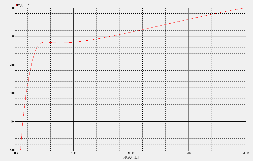
Response curve for HF circuit of π Crossover

I've sent you mail that has a schematic for the π Crossovers, including 500Hz, 600Hz, 800Hz, 1kHz, 1.2kHz and 1.6kHz models. For each, you'll find a chart of values that will tell you a great circuit topolgy for your needs. You can set it for any amount of attenuation you like, and it will give you a nice response curve for compression horns needing top octave compensation.

Previous Topic: Pi Theater 4s at Outdoor Wedding Reception
Next Topic: Has anyone tried the SELENIUM 15PW3CE? looks smoother than emm.
Goto Forum:


Current Time: Fri Nov 29 19:53:43 CST 2024

Sponsoring Organizations

DIY Audio Projects
DIY Audio Projects
OddWatt Audio
OddWatt Audio
Pi Speakers
Pi Speakers
Prosound Shootout
Prosound Shootout
Miller Audio
Miller Audio
Tubes For Amps
TubesForAmps.com

Lone Star Audiofest