| 3 Pi Build [message #62972] |
Sat, 29 May 2010 22:27  |
 rkeman
Messages: 78
Registered: March 2010
Location: Florida
|
Viscount |
|
|
|
Having just completed a set of 3 Pi speakers with 8 ohm AE TD12S woofers and B&C DE250-8 drivers, an important issue has come up. The sound is fairly bright and forward and the speakers show a 5-7 db plateau above 2kHz or so. The speaker is reasonably flat over the band from 40Hz to 1kHz and above 2kHz using 1/3 octave pink noise and 1/10 octave warble tones. Both speakers have essentially identical response curves and other quality speakers have not shown similar behavior using the same measurement techniques in this room. The crossovers are fabricated to specifications using Mills 30 ohm 12w resistors as R1a-d, 28 ohms for each R2 leg (8 and 20 ohm values), and Erse PulseX caps (20 mF, 6.8 mF and 0.47 mF), and Erse 14 gauge coils (1.5 mH and 1.0 mH). Checking everything but the coils with a multimeter yields the expected values. R13 insulation covers one wall, rear, top and two shelf braces as recommended. The polarity of the tweeter is reversed as called for in the design. The front panel configuration, port placement and size and internal volume are all to specification. Is the 3 Pi simply voiced with a prominent high end or is something amiss?
|
|
|
|
| Re: 3 Pi Build [message #62979 is a reply to message #62972] |
Sun, 30 May 2010 11:09  |
 |
Wayne Parham
Messages: 18682
Registered: January 2001
|
Illuminati (33rd Degree) |
|
|
Something is not right. This model is one of the smoothest of the line. You didn't say what horn you were using, but remember that these designs are specific to the parts called out in the plans. You can't necessarily substitute parts without design changes being required.
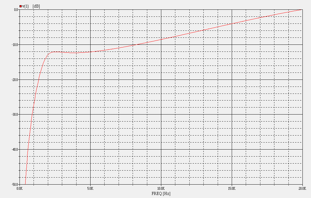
If you've built to spec, you can see a measurement of the same loudspeaker you are building here:
Click on the "Vertical Nulls" link and you'll see the loudspeaker being measured on a S&L WTPro system. The screen shown is a measurement in real-time, scale is 10dB per division. The response chart is ruler-flat, with the only anomalies being down low, a result of room modes.
What measurement system are you using? How is it setup and in what environment? What microphone do you use? From what you said, I think you're using an RTA indoors with white noise. If the system isn't calibrated for the microphone, it may not be flat. I am using S&L and LMS with calibrated microphones and seeing the response shown in the video above.
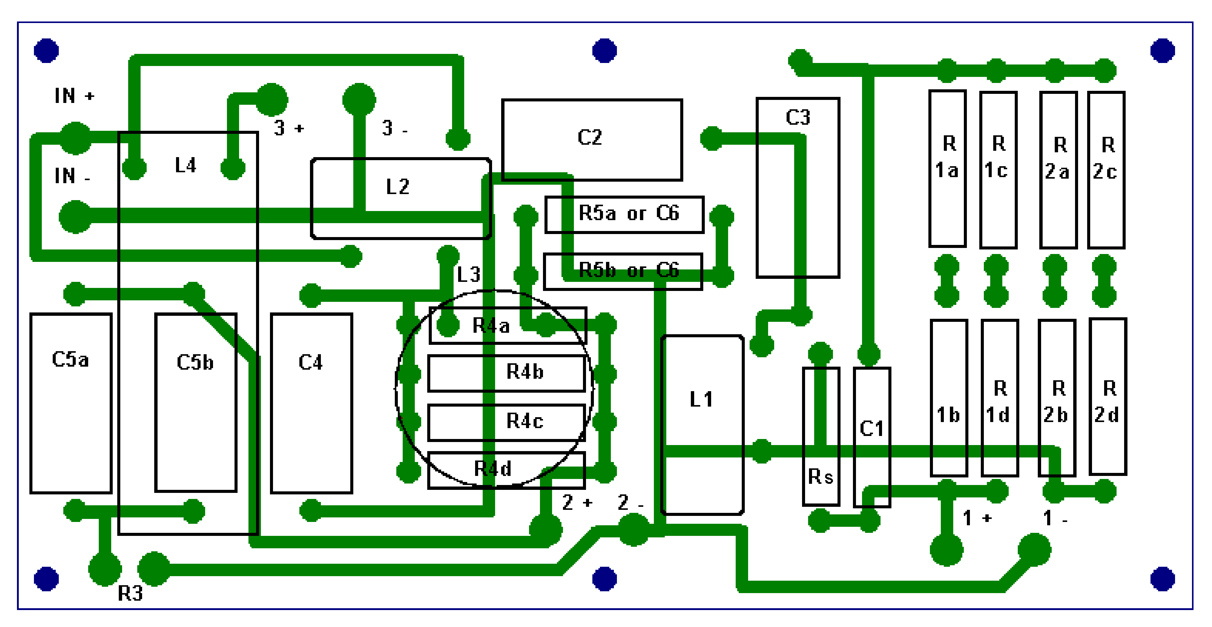
Lets look at the crossover and double-check it too. Obviously make sure the coils and capacitors are in their proper positions, that you didn't accidentally swap L1 and L2, for example, using the 1.0mH in the 1.5mH spot or something like that. The right positions are L1=1.0mH (tweeter circuit), L2=1.5mH (woofer circuit) and the tweeter capacitors are C1=0.47uF, C2=6.8uF and C3=20uF. The woofer circuit has a 20uF capacitor in position C4 and no Zobel.
You said you were using 30Ω resistors in positions R1a,b,c and d. That's good. For R2, you've said you use 20Ω and 8Ω resistors in series/parallel, which should work but we do it a little differently. The plans specify 12Ω for R2a and c and 16Ω for R2b and d. When using Mills resistors, we use 12.5Ω and 15Ω resistors in place of 12Ω and 16Ω resistors. In any case, double check to see that the total R1 (a,b,c,d) network is 30Ω and the total R2 (a,b,c,d) network is 14Ω. Each should be within an ohm or so. You might grab a meter and measure across the total block of R1 and R2 components in-circuit, just to be sure their values are right.
R1/R2 values don't just set attenuation and provide top-octave compensation but they also set the amplitude of the shelf around 2kHz. You can manipulate R1/R2 values to get any amount of output you want in these three areas, semi-independently:
1. overall attenuation (move the whole curve up or down without changing its shape)
2. top-octave boost (increase or decrease the level of the diagonal line up high)
3. bottom shelf amplitude (raise or lower the bottom region between about 2kHz and 5kHz)
The values of R1 and R2 are carefully balanced to provide not only attenuation and top octave CD equalization but also to provide a precise amount of damping of the core splitter filter. This sets the response in the ~2kHz region, setting that initial shelf. Increase damping reduces amplitude around 2kHz, and less damping increases output. This region immediately above crossover is set by damping and is irrespective of the response curve higher up. That's the whole approach of the π crossover.
|
|
|
|


 Posting Rules
 Members
 Search
 Help
Help Register
 Login
Login Get a T-Shirt!


")

