|
Home » Sponsored » Pi Speakers » Build Thread: 2Pi Towers, 6Pi Corner horns (and possibly a sub and center) (Building some Pi Speakers)
| Re: Build Thread: 2Pi Towers, 6Pi Corner horns (and possibly a sub and center) [message #88442 is a reply to message #88057] |
Sun, 15 July 2018 17:19   |
 joshua43214
Messages: 35
Registered: October 2016
Location: USA
|
Baron |
|
|
Once the glue dried, I used a router to flush trim the sides only. The front I sanded just enough to remove the glue, and the back I left untrimmed. The back takes a gasket, delaying trimming as long as possible delays any damage it might receive during construction.
I had saved all the offcuts from the horn to be used as internal bracing. I fitted one brace by trial and error using the bandsaw and a sanding block. Once the brace is close to being a good fit to the taper, one can hold the brace in place against one side, and scribe a line with a pencil laid flat on the other side. Then it is just a simple matter of trimming the edge parallel to the pencil line until it fits properly.
The fitted brace is then used as an angle guide for cutting the remaining braces, by taping the blanks to the fitted brace and running them past the blade.
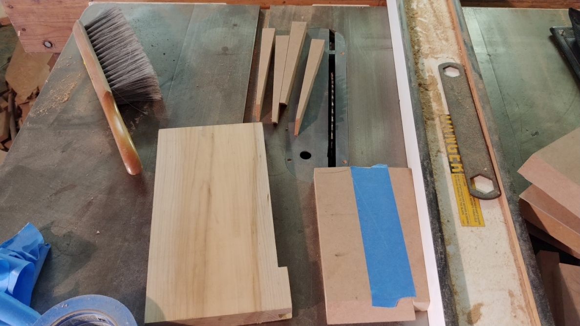
Done wrong, this can be a very dangerous operation. Note the wide part of the guide is closer to the blade. If the tape fails and the part being cut slips, the taper will cause it to move away from the blade. If the taper is run the opposite way, the part will wedge between the blade and fence causing a kick back.
The braces are then trimmed to length. Note the stop block is making contact with the taper, not the end.
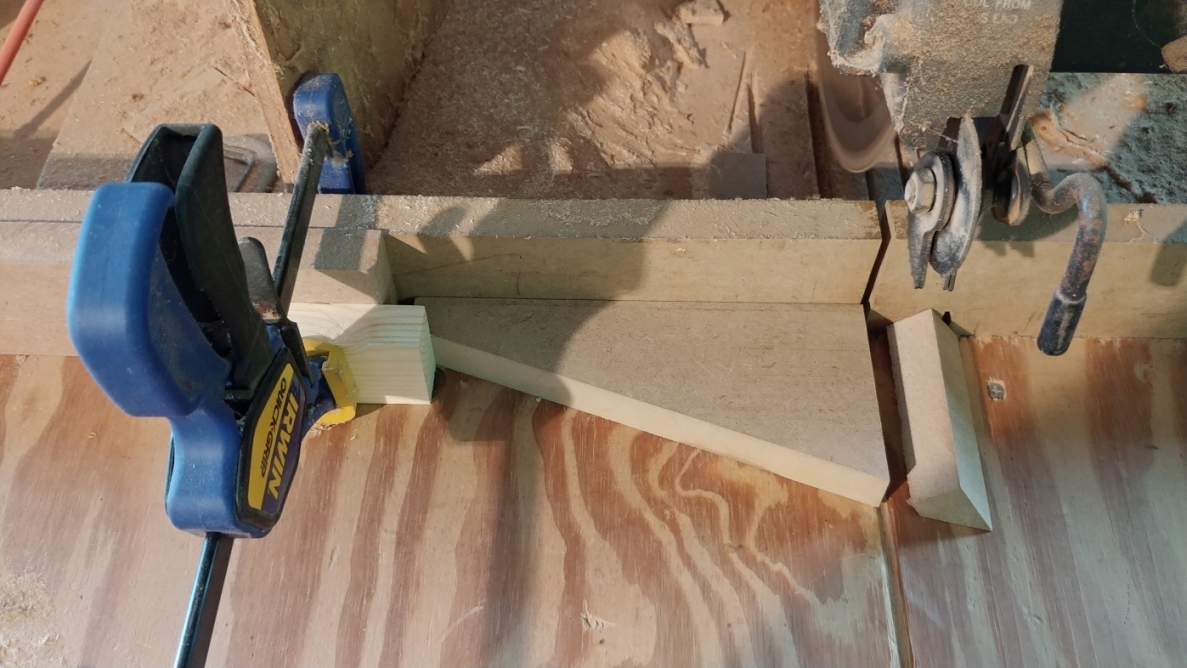
Each horn has a total of 6 braces, 4 for the longs sides, and 3 for the short sides.
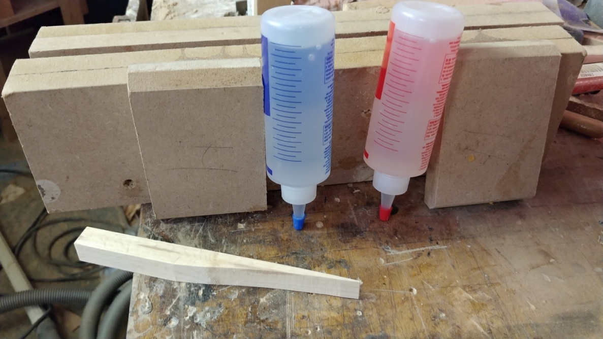
As uniform as these horns came out, they are not perfectly alike. Because of this, I chose to use 5 minute epoxy to glue the braces in. Un-adulterated epoxy is very hard and brittle, so not suited for this application because it might crack from the vibration of the driver. The stuff sold in hobby stores to the model airplane crowd is the right stuff, or the general purpose epoxy sold at the big box hardware stores. People often have trouble measuring epoxy, especially when it comes in tubes because the hardener and the resin have very different viscosities. Follow the directions, if it says equal volumes, do not use a scale. I invert the bottle for a few minutes, and use it in 2 line increments. I make a puddle of hardener (it is thicker) on some brown craft paper, then add the resin directly on top.
The reaction that epoxies undergo is exothermic, and generates heat. If you over mix it, all you are doing is adding energy to the reaction causing it to react even faster. Just mix it until it takes on a whitish color and use it. Once it starts to get stringy, stop even if it means you have to scrape it back off your parts. I had to mix 3 batches to get all the braces in.
I then cut out the fiberglass stuffing. Nothing fancy here, I just went at by eye with a utility knife. Took me all of 10 minutes.
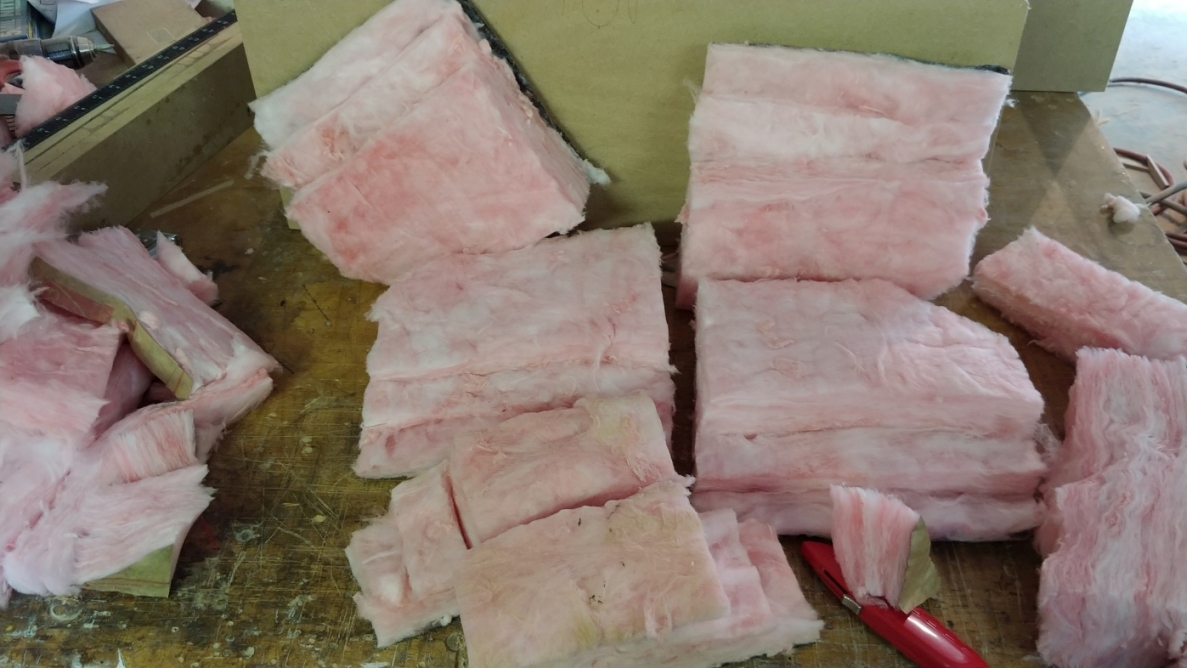
The stuffing needs to go in before the driver mount. I also made sure the bracing would not interfere with the driver mounting screws. This is something that can be done in cad, but I just transferred the positions from the mount itself.
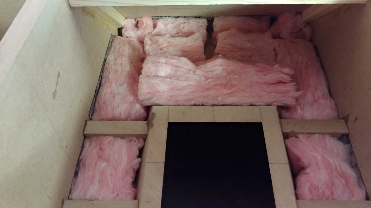
Up Next: Even more Horn building...
|
|
|
|
| Re: Build Thread: 2Pi Towers, 6Pi Corner horns (and possibly a sub and center) [message #88443 is a reply to message #88057] |
Sun, 15 July 2018 17:53   |
 joshua43214
Messages: 35
Registered: October 2016
Location: USA
|
Baron |
|
|
The driver mount should be just a smidge shorter than the box sides otherwise there will be no room for any glue and it will be difficult to put in. I cut mine when I cut the sides, then sanded one edge back until it fit right.
I test fitted the mount, and scribed the throat opening. The holes for the driver mounting screws are laid out from the scribed line. Once again, I took the easy way out and drilled the holes and made the cut out on the mill.
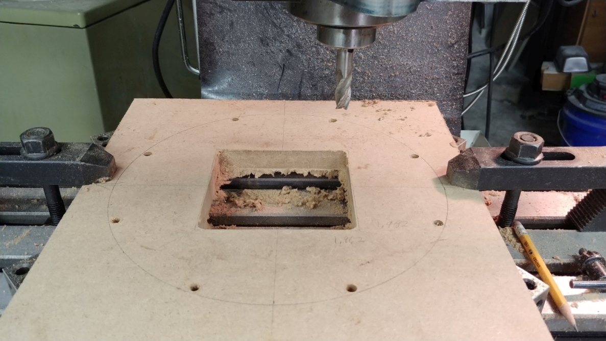
Note I stayed very far from the line. This extra material is important later.
I managed to remember to install the inserts before I glued in the mount. Forgetting this would be a disaster since they cannot be installed later. I also lightly moistened each hole, and added a touch of Gorilla Glue, having these unscrew would also be a disaster.
After gluing in the driver mount, I glued 3/4" (19mm) square pine strips to the top and bottom of the box at the back. These strips will hold the inserts for the back cover. I also glued in some 3/4" (19mm) braces along the driver mount to top/bottom joint. I then taped some brown construction paper inside the assembly to prevent sawdust from getting down into the stuffing.
Using one of the bass bin supports as a sled, I ran the whole assembly through the table saw to trim the excess off the back.
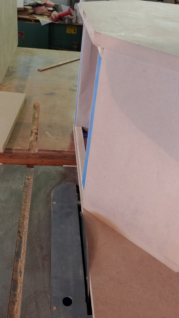
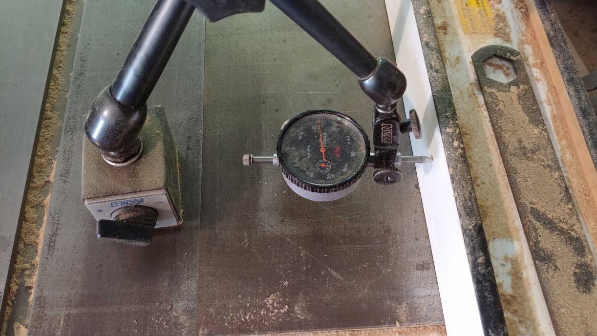
This is when having a dial caliper and dial indicator come in really handy.
I measure how much material is remaining.
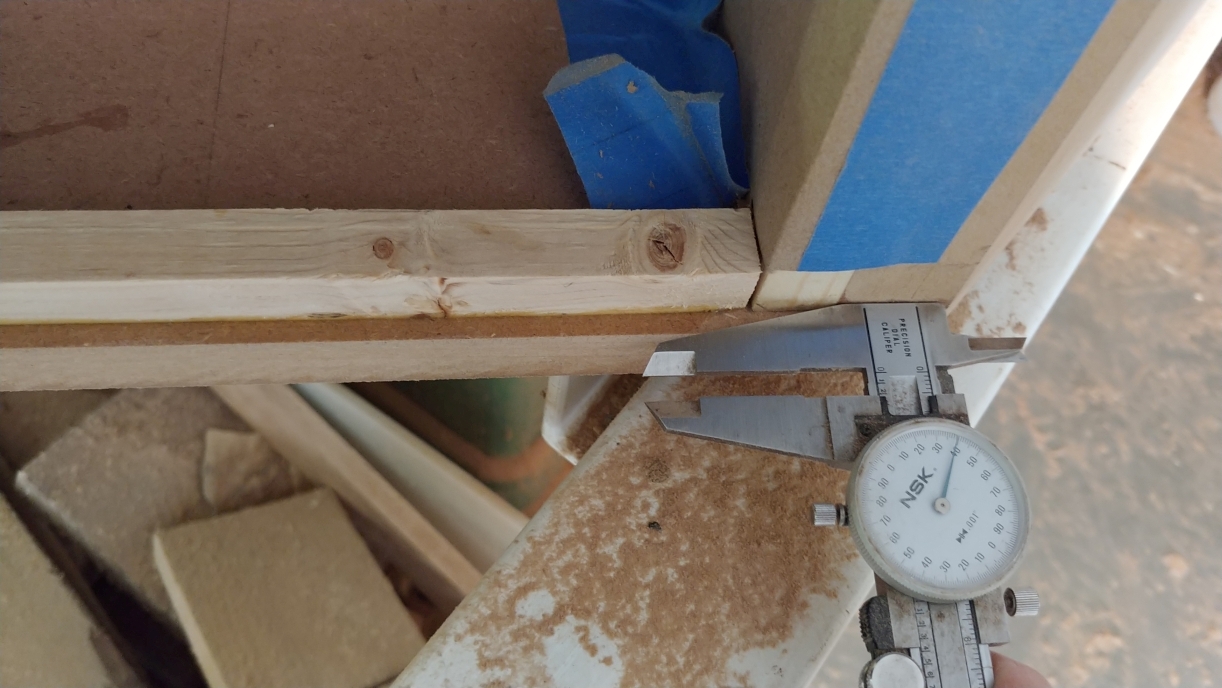
Then use the dial indicator to bump the fence over a few thousandths short of the target distance.
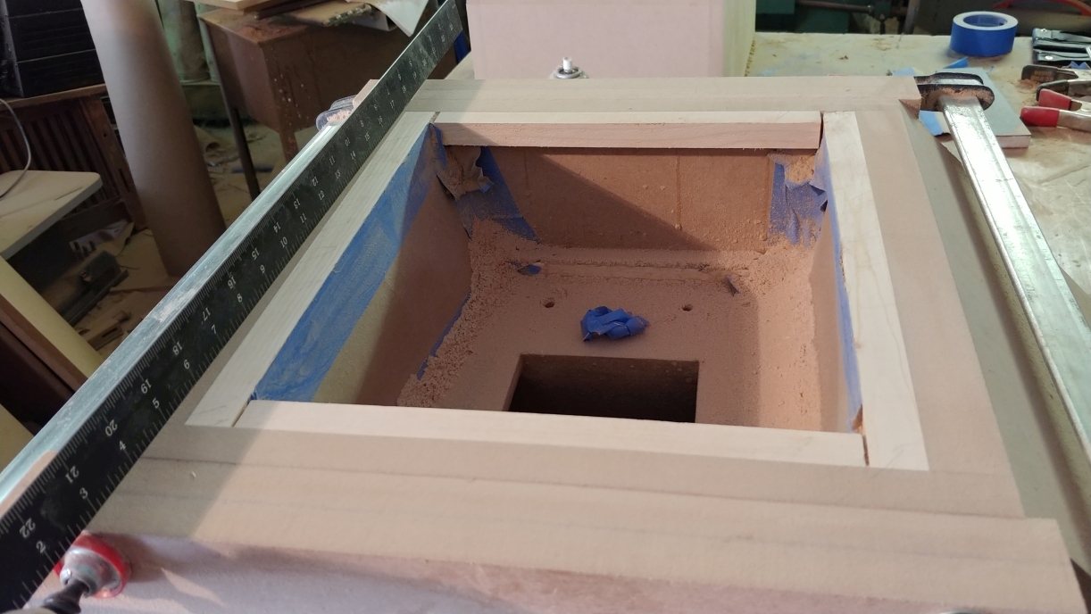
I then placed the assembly mouth down on the table saw, and found the lowest point on the back. I scribed this height all the way around the box, and clamped straight pieces of scrape to the box along the line. Then it is just a matter of sanding and checking with a straight edge until the back of the box is flat. It is not so important that the back be parallel to the front, what is important is the back is flat. A gasket is only as good as the surface it seals. The rear cover will flex a bit, and a rubber gasket will compress a bit, but not enough to make up for very much error.
Up next: yet again another post on the horn...
|
|
|
|
| Re: Build Thread: 2Pi Towers, 6Pi Corner horns (and possibly a sub and center) [message #88444 is a reply to message #88057] |
Sun, 15 July 2018 18:24   |
 joshua43214
Messages: 35
Registered: October 2016
Location: USA
|
Baron |
|
|
Dealing with the throat of the flare is something I spent quite a bit of time thinking about. I read about every paper published for free on horn theory, and learned a huge amount in the process. It seemed self-evident that having sharp edges where sound entered the horn would not be a good thing. This turned out to be a subject that others have done some research on. In the end, I decided to be guided by a whitepaper by Charles E. Hughes for Peavey called "The Quadratic Throat Waveguide." Reading this paper alongside Wayne's own whitepaper on horn theory will probably all one needs to know about horns in general unless you want to take the deep dive into it.
In short, the paper contends that the transition from the backside of the horn, to the inside of the horn should be a circular arc, whose edges are tangent to the back and side faces. The paper goes onto contend that the corners where the sides meet the top/bottom of the horn should be a parabolic profile whose origin is relative to the width of the side at any given point. The first part is simple enough, and can be done easily with a compass, the second part requires real working knowledge of calculus, and implementing will be a nightmare. Fortunately, we are making a 6Pi Cornerhorn, not a Peavey horn. My other research showed that above a certain size diffractions inside of horn become inaudible even when measurable, and that standing waves inside the horn are a far bigger issue. The 6Pi midhorn is just over that threshold for size.
I honestly do not know how much of a difference this will make verses just eyeballing a radius, but it make me sleep better, which makes my girl friend happy, and a happy girl friend makes me happy 
Returning to Fusion 360, I exported the midhorn core to a new design, and created a model just for the arcs.
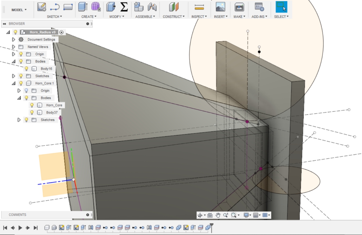
I then created a shop drawing from the new model and printed it out.
I trimmed a piece of scrap to be equal to the distance from the front of the driver mount to the tangent line of the arc, and scribed the lines where the arc should end on the inside of the flare. The extra material I left in the cutout makes it easier to support the block for marking.
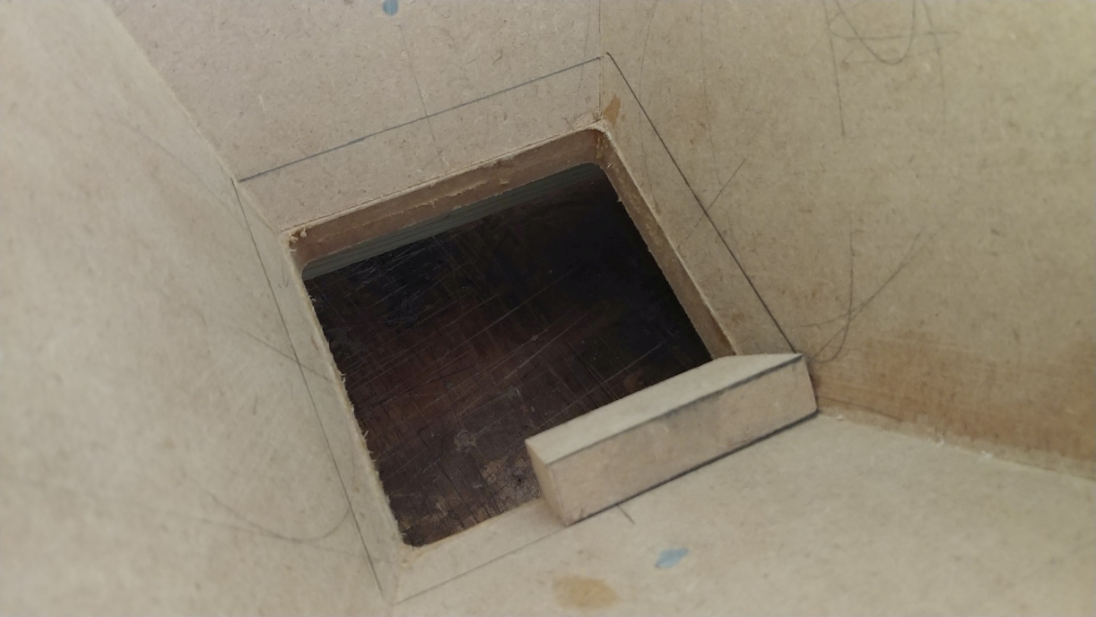
To keep everything nicely consistent, I taped scrap to my sanding block so that it would approximate the arc. techinically, this will form an involute, but they are very similar in shape.
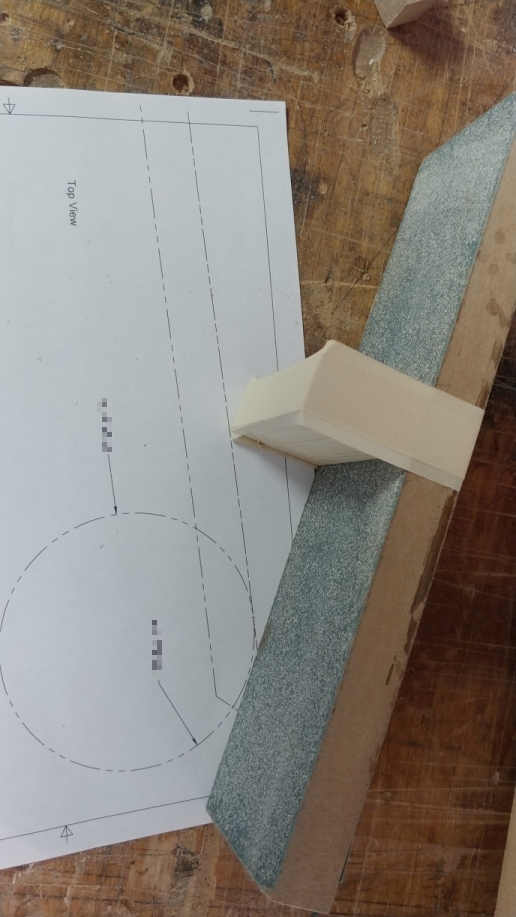
I then glued the paper to some scrap, cut off the excess paper, and used it to check my progress as I went.
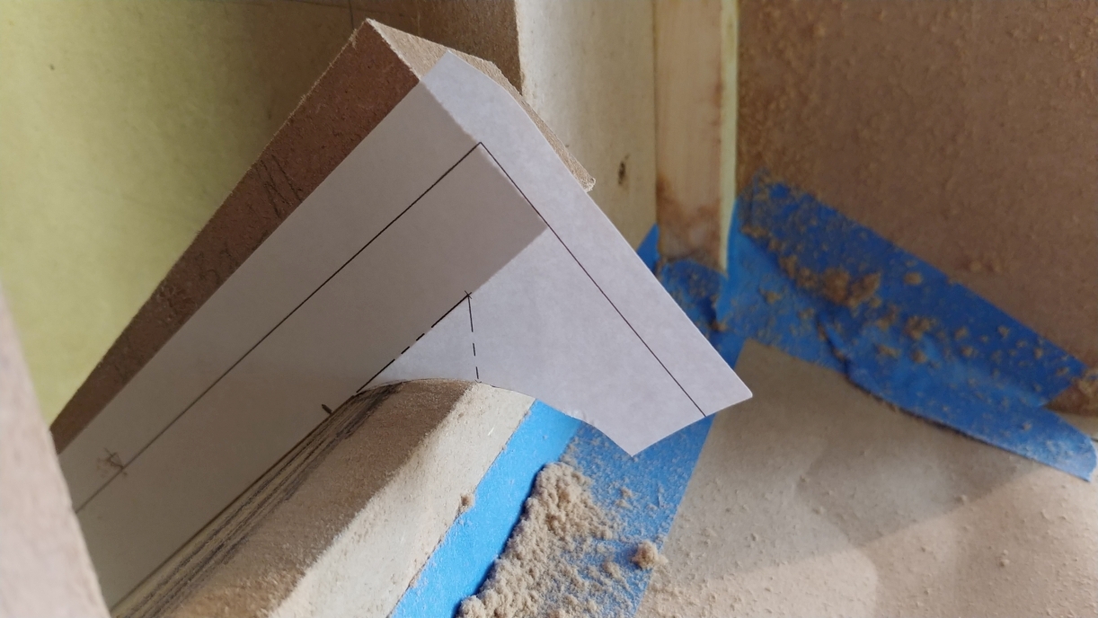
This was another unfun job, but it went faster than I expected.
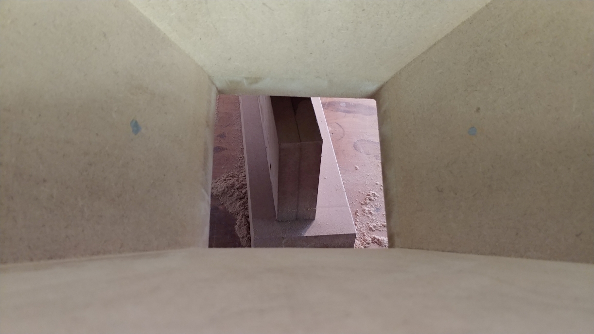
Next Up: the back cover and starting the crossover boxes
|
|
|
|
| Re: Build Thread: 2Pi Towers, 6Pi Corner horns (and possibly a sub and center) [message #88445 is a reply to message #88057] |
Sun, 15 July 2018 19:06   |
 joshua43214
Messages: 35
Registered: October 2016
Location: USA
|
Baron |
|
|
I spent some time trying to figure where to put the crossovers. I know it is common to put them in a box, and set them on the floor next to the speakers. I am not the neatest person in the world, and this sort of thing just creates more mess in my world. I did want ready access to them, so putting them inside the bass bin seemed a bad option. After experimenting in CAD for a while, I settled on putting them in boxes, and mounting the boxes on the back of the midhorn. The pros of this are the crossovers are easily accessible, the box can be used to brace the back panel eliminating the need for a rubber ball behind the driver, and the crossovers are near the drivers making for a clean set up. The cons are that if I need to unplug the midhorn for testing, I will have to remove the box, and the fasteners are pretty expensive.
Because the box bolts to the back of the midhorn, the box is the same size as the back.
I focused heavily on ensuring the front of the box and flare where as square as I could make them, this came at the expense of squareness at the rear cover. Both of them are very slightly out of square.
I began by ripping the backs for the midhorn and crossover box to fit their individual horns. I then taped the back cover and crossover back together, and cross cut them to fit the midhorn. I used layers of tape on the miter gauge to adjust the angle as I cut them. This is much simpler than adjusting the miter gauge, and just as accurate in this case.
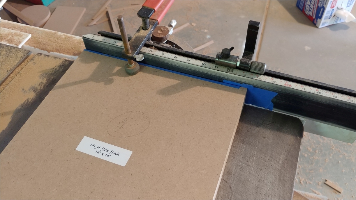
I then marked out and drilled the 4 holes for mounting the box through both parts. The holes in the horn back gets drilled over sized later to take the 1/4" threaded inserts. After separating the parts, I drill the holes for the binding posts.
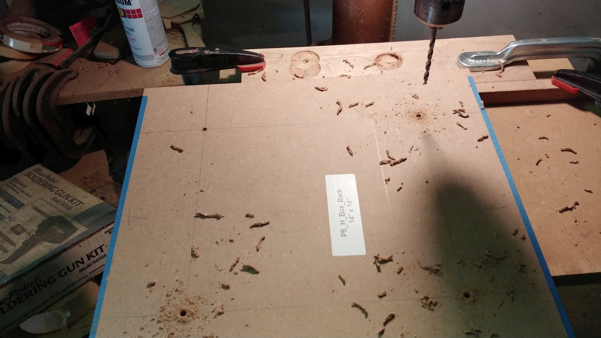
I have a rolling cart that I use for my drum sander that turned out to be just the right height to put under my drill press for drilling the mounting holes for the back cover. This was easier than attaching an oversized table to the drill press. I also have a bench top drill press that would have worked nicely by turning the head around.
I drilled first just one hole that is a tightish fit on the 10-32 screws I used.
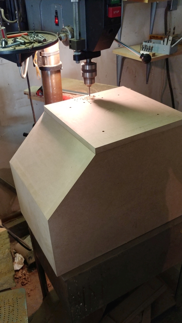
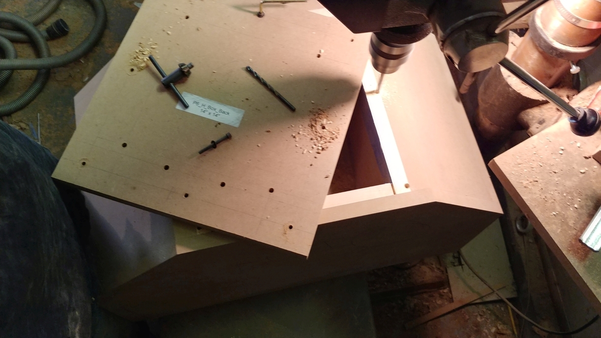
I removed the back, swapped in the correct drill for the insert, and drilled again. I installed the insert, and screwed the back on with one screw. This screw will keep the back correctly positioned as I drill the remaining holes.
I went one hole at a time, first drilling for the screw, then the insert. A bit of a time consuming operation, but it ensures all the holes are well placed.
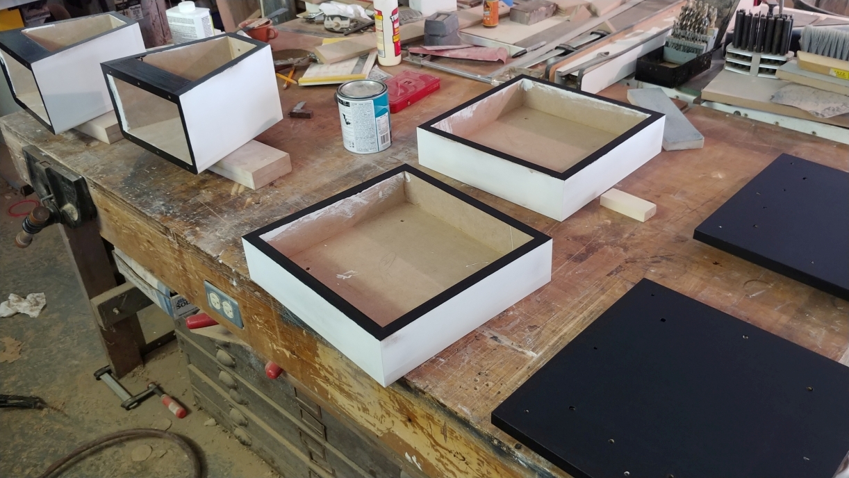
The crossover box is straightforward with sides 2.5' (64mm) tall. I cut the sides to fit the back cover. The cover was not so far out of square that it affected the corner joints of the box sides.
I was sure I had taken pics of them, but I seem to have misplaced them. So instead I offer a pic of the parts when I was painting the edges that are hidden. As a bonus they include a sneak preview of the tweeter boxes.
This concludes the construction of the midhorns.
Up Next: The Tweeter boxes.
|
|
|
|
| Re: Build Thread: 2Pi Towers, 6Pi Corner horns (and possibly a sub and center) [message #88446 is a reply to message #88057] |
Sun, 15 July 2018 19:37   |
 joshua43214
Messages: 35
Registered: October 2016
Location: USA
|
Baron |
|
|
I designed and discarded a number of tweeter enclosures. The problem is that the horn itself is simply ugly and utilitarian, and putting an enclosure around it just makes it that much more obvious you are hiding something.
In the end, I just decided to embrace its ugliness, and wrap it in a box that looks like it is serving some puropose.
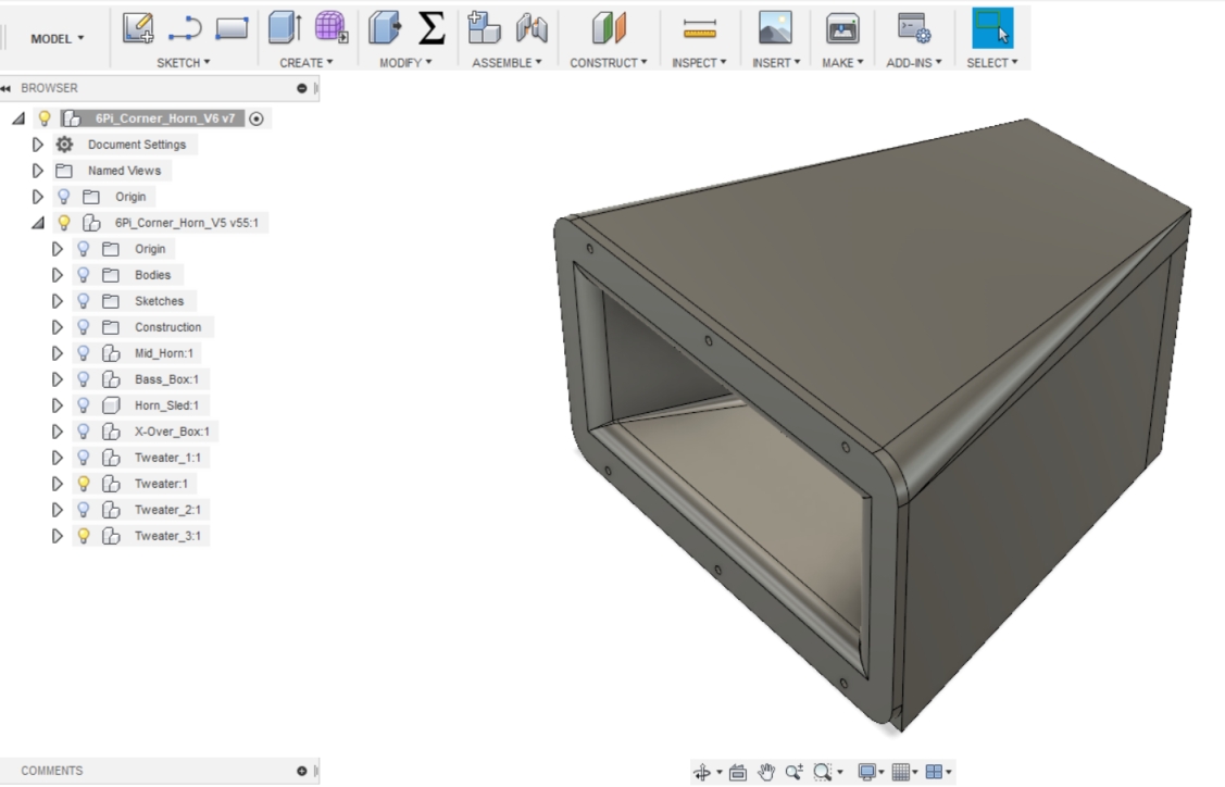
The tweeter boxes are "as built." I began by marking out the dimensions of the top. I used a piece of scrap that I ripped to be parallel to set the angle of the miter gauge. The scrap is held against the rip fence, and the miter gauge is adjusted until the other edge lays on the pencil line.
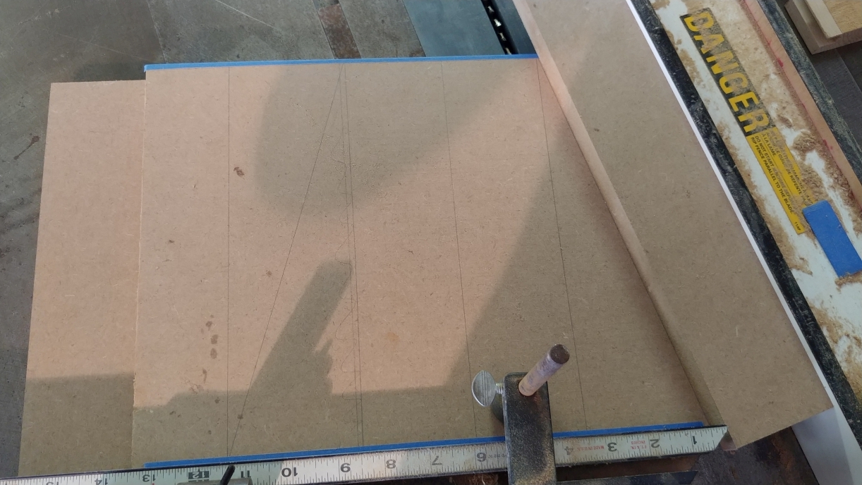
The fence is then moved out of the way, and the tops are cut to the line.
The driver is large enough that a relief is needed in the top. I cut the relief with a dado. A bit of trial and error was able to locate the position of the material so the relief would be centered.
The pic below has all the details. A stop is clamped the to the fence with a large C clamp. A piece of scrap is clamped above the work to prevent it from shifting upward when the dado head is raised. The work itself is held in place with a bar clamp. A large piece of scrap is clamped at the front of the saw as a last safety device should the worst occur, and it will prevent the work from hitting me in the face as I kneel to raise the blade.
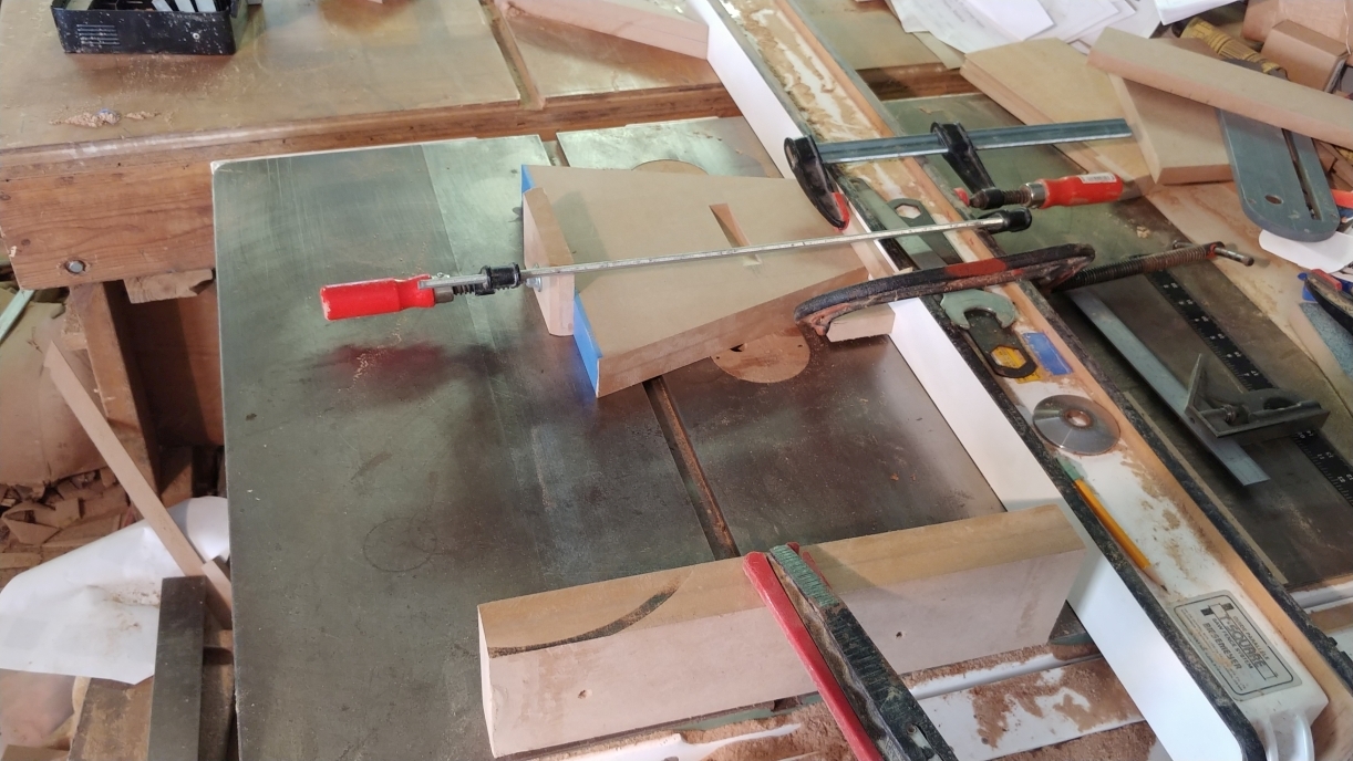
After the cut is made on both sides, the fence is moved over about 3/4" (19mm) and the operation repeated.
Once the angles are cut, the top itself is then used to set the blade angle for cutting the sides.
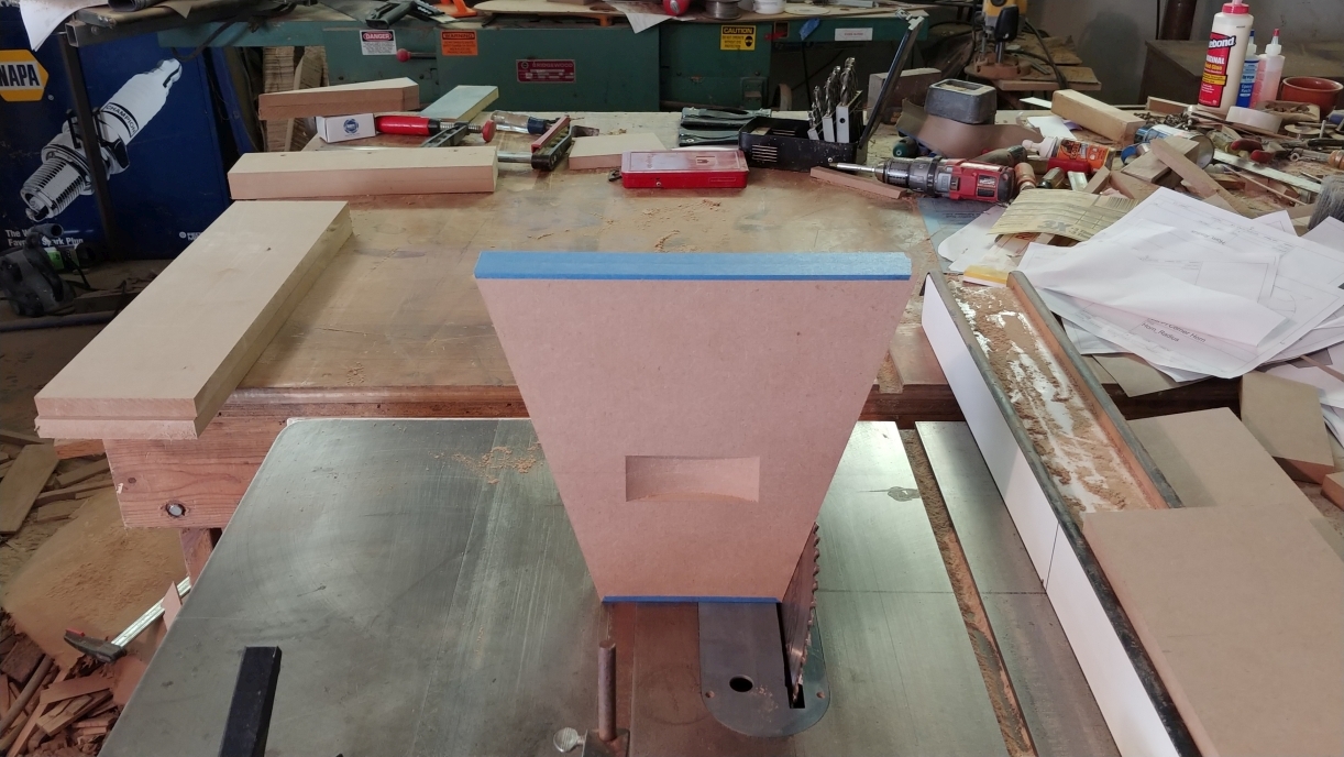
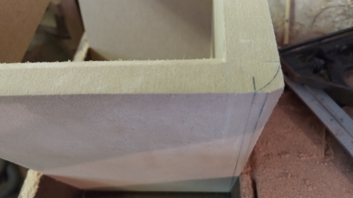
The bottom is little more than a brace to keep the front end of the sides positioned, and the back is just a cap. After glue up, I used the horn to scribe the radius at the front, and sanded the taper with a long hard sanding block and 80 grit sandpaper.
|
|
|
|
|
|
|
|
Goto Forum:
Current Time: Tue Jan 27 21:28:38 CST 2026
|


