|
Home » Sponsored » Pi Speakers » Build Thread: 2Pi Towers, 6Pi Corner horns (and possibly a sub and center) (Building some Pi Speakers)
|
|
| Re: Build Thread: 2Pi Towers, 6Pi Corner horns (and possibly a sub and center) [message #88173 is a reply to message #88172] |
Wed, 13 June 2018 11:46   |
 |
 Wayne Parham
Messages: 18985
Registered: January 2001
|
Illuminati (33rd Degree) |
|
|
Seriously cool build thread, Josh! I've been meaning to say a few words, but I've been slammed lately. So I just read without comment. But here are the things I've been meaning to say, or at least thinking about as I read your notes:
As John said, the six π cornerhorn is actually a smidge taller than the seven π. But it's only just a little taller - Less than 2". So I didn't say anything when I read your post about that. They look exactly the same to the eye.
Same with the three π and the four π speakers. If they're not side-by-side, they look the same size. But the three π is slightly larger.
It's just the tuning required for the drivers I've chosen. Both have an alignment that is slightly overdamped, just the way I like it - Controlled. The system can't shift towards underdamped (peakyness) even when the power levels are high for extended periods.
The threads in the "Models, Upgrades and Driver Characteristics" section of the FAQ talk about all that stuff in more detail so I won't belabor it in your build thread.
Lastly, I saw that you would have liked gold "π" decals on your tower twos so I sent a couple in the package with the three π sub kit. I also sent the replacement crossovers for your cornerhorns.
I'm still amazed how much damage those parts suffered. UPS does a pretty good job, but I have to make claims in about one out of every thousand shipments. So I'm hoping I'm good for two thousand shipments 'cause you had two packages damaged. 
|
|
|
|
|
|
|
|
| Re: Build Thread: 2Pi Towers, 6Pi Corner horns (and possibly a sub and center) [message #88177 is a reply to message #88057] |
Thu, 14 June 2018 21:30   |
 joshua43214
Messages: 35
Registered: October 2016
Location: USA
|
Baron |
|
|
The horn flare requires the sides to be cut at a compound angle. The work must be fed through at an angle, and the blade itself must be angled. There are a number of ways to accomplish this, all have pros and cons. The number of methods shrinks rapidly when they are constrained to a high level of precision and consistency. Ideal methods will use a single set up on the saw.
Before I began cutting parts, I took the time to make sure the rip fence was parallel to the blade, and that the miter gage was square. I use the dial indicator to adjust the fence. I turn off the magnetic base, and hold the base firmly against the fence with the plunger near the gullet of one of the teeth on the blade. Zero the indicator, then move the base up the fence and check the far side of the blade. Best practice is to mark the gullet with a felt tip pen, and use the same gullet for each check. I prefer this method to using the miter gage as a mount for the indicator.
To square the miter gage, cross cut as wide a piece of scrap as you can. Tape a piece of paper to the table next to the rip fence. Hold the reference edge against the fence, and strike a line along the edge that was cut. Flip the part over front to back, hold it against the fence and strike another line alongside the first line. The difference between the two lines is the double the error.
These two checks are the first of the critical things that I was fussy over.
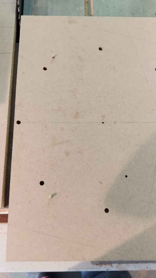
Accomplishing a single set up is best done using a sled that positions the work, and once the rip fence and blade angle are set, all the cuts can be made. My sled is just a piece of MDF with 3/16" (4.5mm) brass pins spaced exactly 10" (25.4cm) apart. To get the pins "perfectly" parallel to the fence, I ripped a piece of scrap approx 2.5" (64mm) wide, and placed it ontop of the sled between the pins and the rip fence, then just ran the sled through the saw. The fresh cut edge is now the edge used against the rip fence for cutting the flare parts.
The image shows the sled on the saw. Note the larger holes are the hole pattern for the bass bin driver, so the sled does double duty as a drill guide.
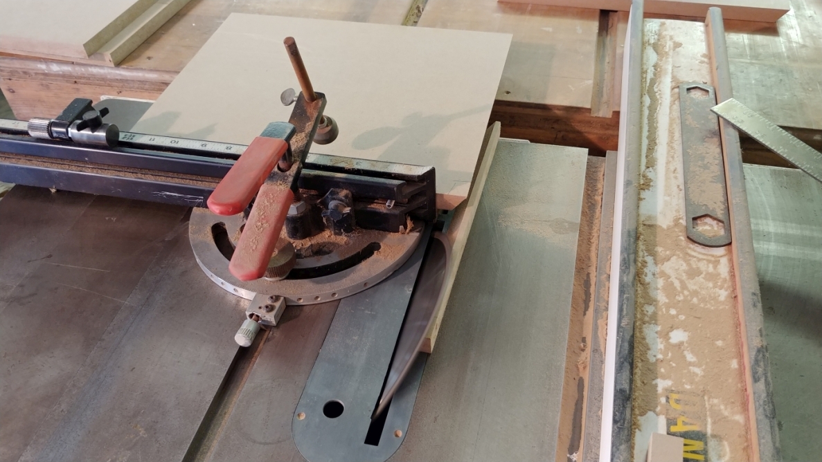
The flare sides are trimmed to length. Note the work is elevated off the table saw so the tapered edge on the other end can register properly on the miter gage stop.
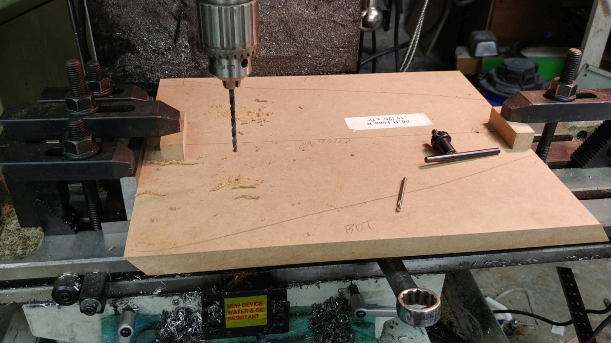
Three holes are drilled in each horn flare side. These holes do not need to go all the way through, but mine do. They are filled later with 5minute epoxy.
I used my mill to drill the holes. These holes need to be very accurately placed, and my mill has a DRO that makes it painless. This can be done with a compass and a trammel. I will go into details in my next post about locating the holes accurately with primitive tools, and finding the cut angles.
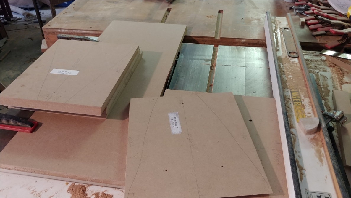
The flare is then placed over the pins, and the edges are ripped.
Note the large piece of MDF clamped on the left side of the blade. This is to prevent the offcut from falling onto the angled blade and getting kicked back.
The part is then reversed, and the other side ripped.
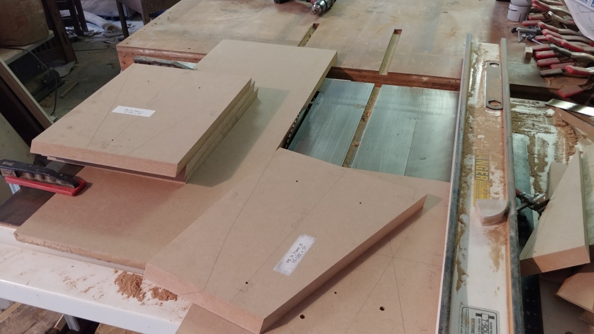
You might notice that there are no clamps holding the part to the sled. None are needed. The holes are drilled to be a tight fit, and hand pressure is more than enough to hold it down. In practice it feels no more dangerous than making any other rip cut.
Up next: Finding the angles and marking the holes.
|
|
|
|
| Re: Build Thread: 2Pi Towers, 6Pi Corner horns (and possibly a sub and center) [message #88178 is a reply to message #88057] |
Fri, 15 June 2018 00:54   |
 joshua43214
Messages: 35
Registered: October 2016
Location: USA
|
Baron |
|
|
This next part is difficult to describe in words. I will do my best, but I tend to fall into the pedantic style that science and math papers are written in, so please accept my apologies in advance if this post is a difficult read.
Many of you probably noticed the flare sides where rough cut as rectangles rather than as trapezoids. At first glance this might appear to be grossly wasteful of materials. It is, but the offcuts will be used later as bracing, mitigating some of the waste. The main reason they are cut as rectangles is so that the mouth and the throat are parallel to each other. This would be very difficult to accomplish otherwise. This ties back to my earlier post about constantly asking myself "how am I going to cut that, and how am I going to install that." Planning the cutting and assembly during the design stage is a huge benefit.
I will go ahead and describe part of the process for creating the CAD model for the flare in Fusion 360. My feeling is that most people who are willing to take on a speaker cabinet project will probably be also interested in using CAD. CAD has a bit of a learning curve. I dumped many thousands of dollars into CAD programs since the 90's, and I have found that Fusion 360 is the best all around tool for the work I do (and it is free).
I began by modeling a core that is the inside of the flare.
The image shows the core with the right side and the bottom. The base sketches for the core are visible inside the core.
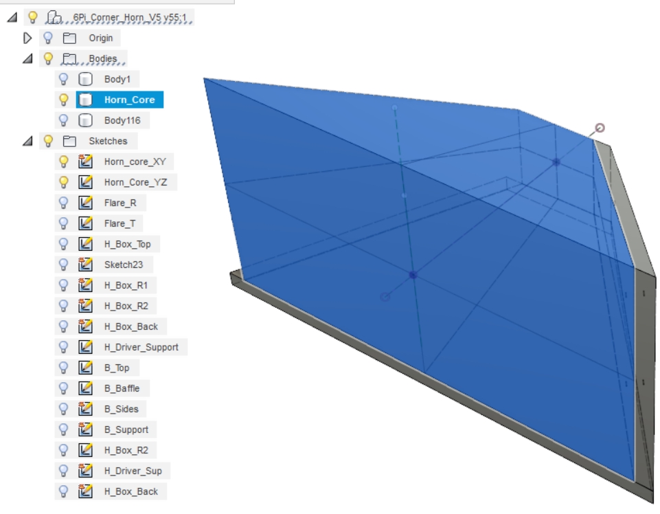
To model a side, I selected a side of the core as the reference plane, then just sketched a rectangle bigger than the core and extruded it to my material thickness. The adjacent faces of the core are then used as slicing planes to split the side, and the extra parts removed.
I found that I could not get the dimensions and angles in the plans provided by Wayne to work together. I am providing the link to the thread I started again for reference.
A pro-tip on modeling. When I drew the horn core, I began by making the base sketch for the core in the XY plane. I stopped the sketch without extruding it. While making sure the first sketch was visible, I started the base sketch for the YZ plane. By doing this, the first sketch will "auto-project" into the new sketch allowing one to constrain the intersections of the lines to be coincident. That way, when a change is made to one base drawing, it will force the other base drawing to adjust to it. Once both base drawings are completed, I returned to the first drawing and extruded it oversized. I then extruded the second drawing also oversized (ensure you are making a new body). The two 3D bodies are then used to split each other, and the offcuts removed leaving nothing but a single body.
One of the limits of Fusion 360 is that it is purely a 3D modeling program. 2D modeling is limited to base sketches that are extruded into 3D shapes. The software is meant for producing models that are made either by 3D printing or CNC machining. As such, the tools for producing shop drawings are limited since shop drawings are 2D.
When the 3D model is imported into the tool for generating shop drawings, all the parts are projected from the cardinal directions of top/side/etc. Parts that are not planar with one of the cardinal views will appear angled or foreshortened in the drawing space. Search YouTube for tutorials on creating custom views (it is very simple), and select the appropriate view when creating the shop drawing for the horn parts.
The angle that is needed for the saw blade is referenced to the bottom face of the flare, and is measured along the line perpendicular to the cut edge. There is no reliable way to create this reference in the shop drawing space.
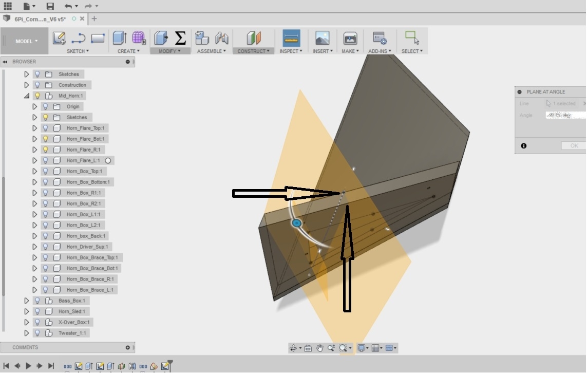
I found the simplest method to get this angle was to sketch a line on the inside face of the right side perpendicular to the cut, and use that line to create a new plane at a 90 degree angle. I then split the part with the plane, and copied the new part to a new model space, and used "undo" to remove all the edits (don't forget to break the link to the old model). The new part was exported to the drawing space as its own file, and my angle measurements taken from there. The angles for the mouth and throat can be taken from the main drawing.
Where to place the three holes for the pins will depend on your tooling. The digital read out on my mill resolves to 0.0001" (0.0024mm), so I just put them where they looked ok. All of the dimensions of the horn work together, so it is important to cut and measure as accurately as possible. Your dial indicator will scribe marks very accurately up to its capacity, but making marks 12" or so inches from the edge are problematic.
Here is my suggestion for making the layout. This assumes you acquired a machinist combination square that does not suck. It is a really good idea (like really good) to go through all the horn parts and mark all 4 edges on both faces right/left/top/bottom/inside/outside, and to group them as horn #1 and #2.
Cut the mouth and throat angles, cut the parts as close as you can measure. Reading glasses make nice magnifiers when using precision rulers (I think I forgot to include a 24" machinist scale in the tooling list). Strike a line perpendicular to the mouth bisecting the part. The 12" scale that comes with the combination square can be used to place the hole closest to the throat. Use a dial caliper to scribe a line parallel to the mouth that passes through point A in the pic below. Set the trammel to 10" (check and double check this, get fussy). Strike an arc across the part with the point near the throat and the center. Use the dial caliper to scribe the points closest to the mouth (distance H). Those of you without a flag on the Moon will have to use whatever metric dimensions are standard on tools in your location.
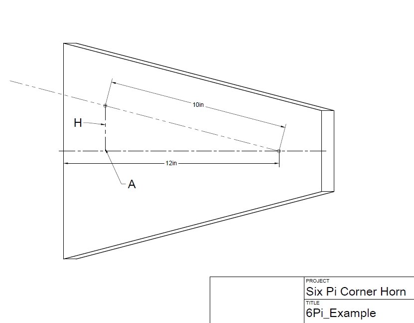
Lightly center punch, and drill with a drill press. I like to use a center point in the drill press to locate the part, then swap in the drill bit. It takes a bit of extra time to swap out the drill before each hole, but there is only 12 holes to drill. Following any method similar to this reduces you to making one questionable measurement (the 10 distance for the trammel), but this distance is only measured 1 time. Even if it is off a bit, the horns will be identical to each other.
An argument for cutting the mouth and throat angle first, as opposed to leaving them square and trimming them later: If the mouth and throat are left square, it will be more difficult to align the top to the sides. Trimming later requires sanding a substantial amount of MDF away, and it will be difficult to ensure the entire face of the flare is flat because of its size. Cutting the angles first does require an extra machine set up, and leaves you referencing from a sharp and fragile edge, but saves time and increases accuracy at the same time.
Use a precision protractor to set the table saw blade. It is vitally important that the protractor be perpendicular to the blade when the measurement is made. I use the miter gage to hold it square. Put a light at the back of the saw, and see how much light leaks between the blade and the protractor. Slide the protractor over, and then back to the blade to double check. This is a point to get fussy over.
At this point, you should have horn sides that are cut to size on all 4 edges, and tops/bottoms that are cut only at the appropriate angle at the mouth and throat.
The flare top and bottom are identical, so I will only talk about the top from this point forward.
Using a framing square (you did Google up how to square a square, didn't you?), bisect the inside face of the top using the mouth as the reference, and taking care the square is referenced on the edge and not on the bevel. Cut some scrap exactly 4.5" as spacers for the horn throat. Use a compass to draw a 4.5" circle near the throat on the bisecting line. Very carefully measure out from the bisecting line the distance to the outside edge of the side, and set the trammel to this distance. Use the trammel to repeat these marks to all the tops and bottoms. Doing this will ensure the horns are identical even if your measurement is slightly off.
Mark a line on the outside of the top that will be directly over the center line of the sides.
Clamp the spacer using the compass circle to get it aligned. If you took your time and where very careful, the throat will be laid out exactly over the center of the mouth.
Dry assemble the horn. It took some playing around to figure out how to hold everything together.
Get the whole horn lined up. With some patience, you will find that it will come together properly. Carefully drill a hole for a 1/4" (5mm) dowel near the throat. Trim a piece of dowel, sand it enough that it can be lightly tapped in with a mallet, and then re-align everything (it will have shifted when you drilled). repeat until you have a pair of dowels on each glue joint (8 total). Plan to spend some quality time doing this.
Line the drill up carefully, there is a strong optical illusion that will lead you astray.
Once all the dowels are in, drill holes for #10 screw threads. Dismantle the horn and drill out the screw holes in the top to clear the threads. Counter sink the holes on the inside of the joint.
Dry fit the parts again using screws and dowels. Tighten the screws just enough to pull it together. inspect closely for gaps or poor fitting. If all went well, you should see no issues. If the joints are not well fitting, you will have to clean them up by hand with a sanding block.
Apply glue and screw it all together. Measure corner to corner at the mouth to make sure the assembly is square. Yellow glue is a good choice with this. If the glue joint is not tight, use epoxy. Do not use polyurethane glue on a poor fitting joint. Polyurethane glues are very weak on joints with gaps, and they are highly porous because of how the expand.
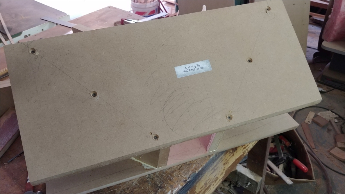
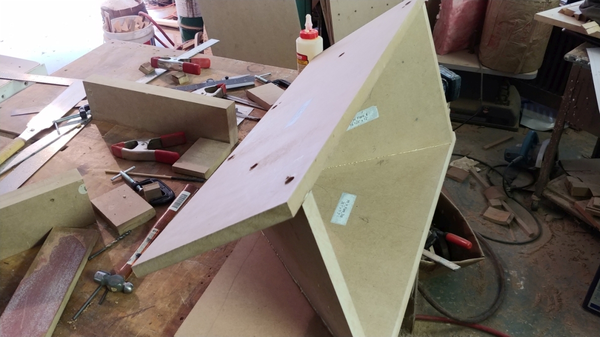
Make sure you remove the 4.5" spacer before it gets glued in place. After about 40 minutes, clean up the glue with a chisel.
Remove the screws and trim the top and bottom flush with a handsaw.
Congratulations, you just built something awesome.
Many years ago I subscribed to Fine Woodworking Magazine (when it was still a mag for professionals). Every month they would feature a "Master Class" where some master craftsman would make something awesome. One month, the feature was about making a feed trough. Is it essentially the same thing as this horn flare only about 3 times the size. Everyone was amazed at how difficult the project was. It turns out that there was a class of woodworkers similar to coopers who did this type of work. It is difficult enough that specialists existed at one time for doing it.
Up Next: The Horn box
|
|
|
|
| Re: Build Thread: 2Pi Towers, 6Pi Corner horns (and possibly a sub and center) [message #88434 is a reply to message #88057] |
Sat, 14 July 2018 13:10   |
 joshua43214
Messages: 35
Registered: October 2016
Location: USA
|
Baron |
|
|
Hello everyone, please accept my apologies for the long delay on continuing this thread.
Along the way to finishing the project several things happened that took away my time on one hand, and took the wind out of my sails on the other. I continued to have issues with the paint, I will go into detail later, but I found it extremely hard to continue to muster enthusiasm for a project I was already getting tired of knowing that I was going to have real issues with the final finish in the end. My experience with the 3Pi Subwoofer only put me off more (more later).
On a more positive note, I was able to sneak a nice trip to the Painted Rocks area of the Upper Peninsula, and took a horizontal transfer where I work. I have the same title and description, but I am taking over a brand new lab and all that entails. The new position also came with a nice pay raise, and very real opportunity for further advancement. I don't recall if I mentioned it already, but I hold degrees in Molecular Genetics and Mathematics, and work in a semi-academic research capacity. The down side is a lot of hours until I can get everything working as it should, and by then we will have 2 post-docs I will have to nurse along 
Also, if you could hear my 6Pi Cornerhorns, I am sure you would also prefer to relax and enjoy the music rather than write a build thread...
That said...
We interrupt this 6Pi build thread to knock out a 3Pi Subwoofer...
The 3Pi Subwoofer is truly a weekend project, and is quite a simple build. If you are looking for a good project to get your feet wet, this, or the 1Pi speakers are an excellent choice.
After a brief email exchange with Wayne over what plate amp to chose, I settled on the Dayton Audio SPA250 from Parts Express. The Eminence JOB12 that the Pi3 Sub is built around is a serious beast, and I was worried about pairing a 250W amp with a 400W driver. There is a huge price jump when you cross the 250W threshold, and I did not want to spend a ton of money on an amp whose primary purpose will be LFE (the 6Pi's do not need a sub). I suppose I should be clear that Wayne did not utter even a breath of approval for this particular amp, he just assured me that the wattage would be more than adequate. Those of you have sought Wayne's advice on anything not sold by Pi Speakers will know that getting him to voice an opinion is like trying to pull teeth from a rooster (for good reason imo).
I still took the time to model the sub in Fusion 360, which saved me from a major issue. The port tube runs nearly the entire depth of the enclosure, and it would have hit the plate amp. I had to move the plate to the upper half of the back to avoid this.
I used "as built" construction for the entire project, and only a handful of critical dimensions are cut before assembly. The 3Pi Sub is really big which makes cutting square edges a bit of a challenge.
When I cut the parts for the 6Pi bass bin, I made a special square to use as a router guide to cut all the parts to identical length, I repurposed this square for squaring up the baffle and rear panel. I know I have not yet written that part of the 6Pi build, I will hopefully get it posted before too long. It is not a complicated thing, just some scrap MDF glued together with 2 edges parallel and both square to a third edge.
I had the store I purchased the MDF from rough cut the parts - the 3Pi Sub needs almost an entire sheet of MDF. I laminated the baffle the same way already described for the 2Pi's. I took extra care to make sure I did not put the clamping screws where it would cause havoc with any of the cut outs. After the baffle dried, I cut two edges parallel on the baffle, the back, and both sides using the table saw. I then cut one edge square on only the baffle and the back with the above mentioned jig. I then cut the last edge by putting the freshly cut squared edge to the rip fence that had been left undisturbed from cutting the edges parallel. The remaining edges on the sides are left rough cut.
A word of caution here. Rip fences are for ripping, and this last cut is a cross cut. Cross cutting with a table saw is extremely dangerous. The parts are large enough, and the baffle heavy enough to mitigate some of the danger though. Unless you have had enough things go sideways on the table saw so that you know what to avoid, I suggest taking the extra time to trim the last edge with a router or circular saw.
Once the baffle and back where cut, I used the all the same methods to cut the driver and port holes as above. I used a jig saw to cut the plate amp hole.
I then glued up the baffle, back, sides, and bottom in one go. I just used my eyes and fingers to get all the overhangs even. There is no need for super accuracy here. A box this size will have to be very out of square before it is noticeable, and it will have no effect on the sound at all.
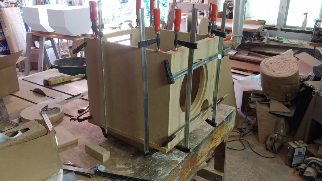
After 45 minutes, I removed the clamps, cut 2 pieces of scrap to support the port tube, and used epoxy to glue the tube into place.
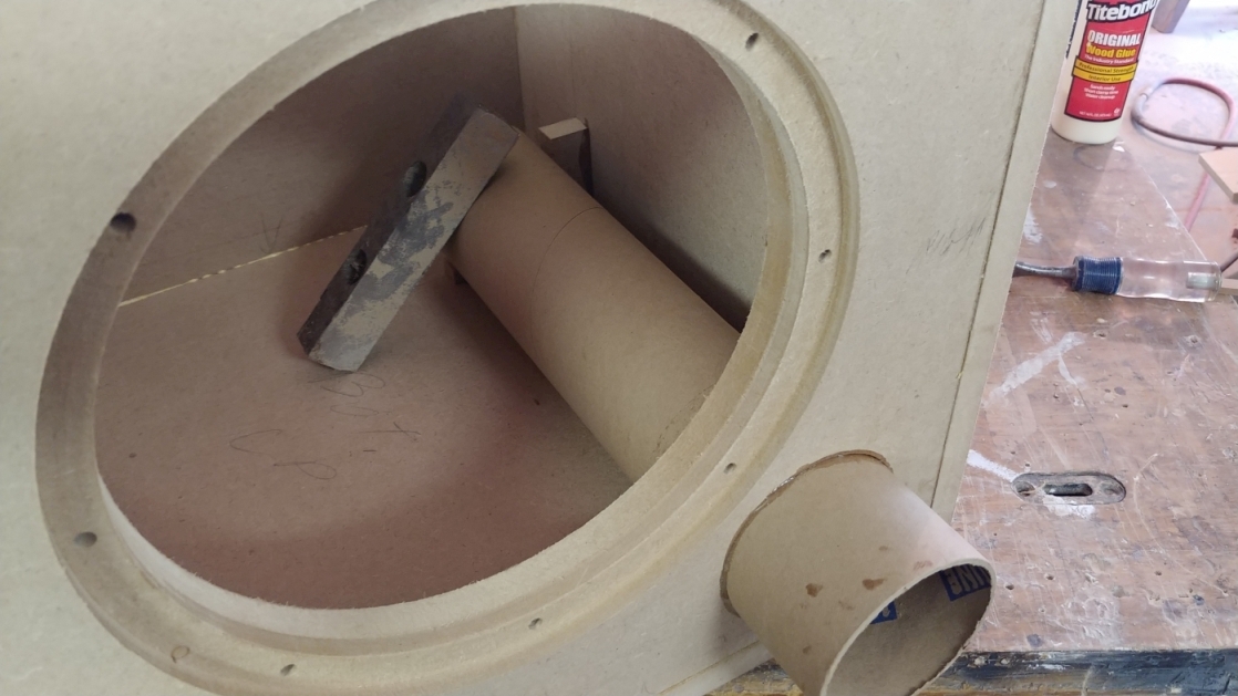
Note the piece of steel scrap used a weight to "clamp" the port to the braces.
I then cut 1x2 pieces to size as braces. All of these are spring fit, and require no clamping. To get the short piece that spans the middle in, I used clamps to flex the longer cross braces back so I could fit the shorter brace in without scrapping off all the glue.
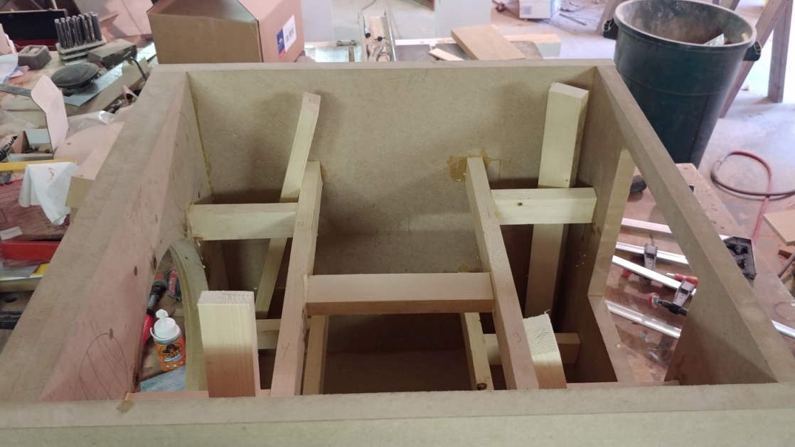
I then glued the top on and left it to dry overnight.
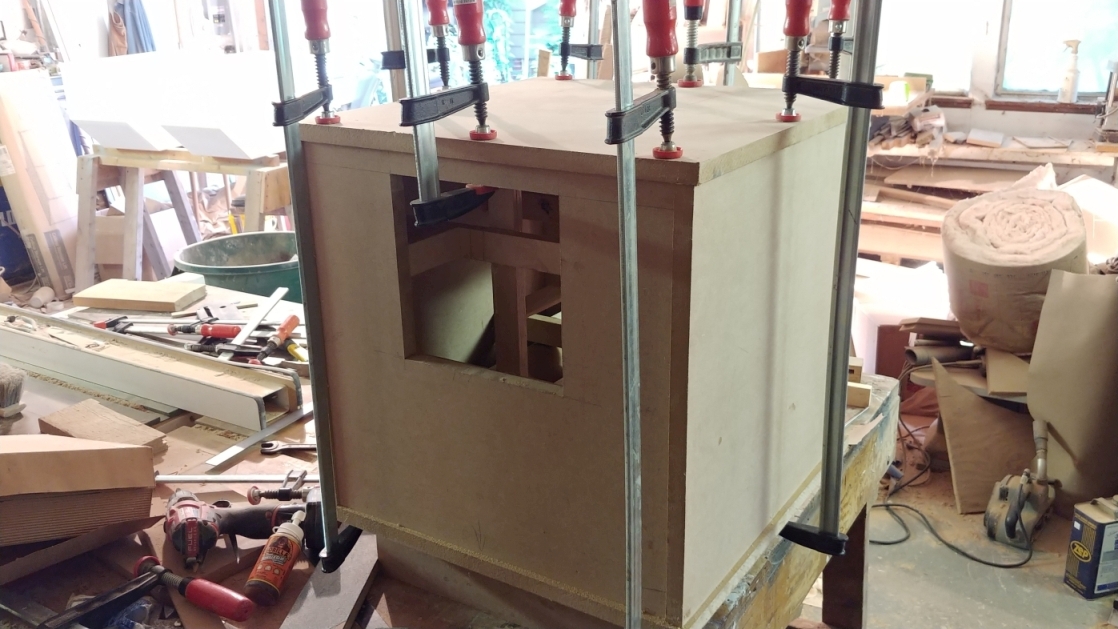
The next day, I used a handsaw to trim the port tube back, and flushed all the edges with a router. At this point I just moved the sub into the house and put it into service.
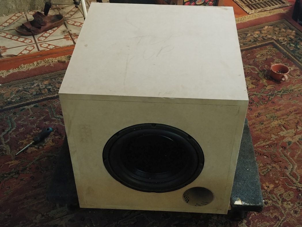
Note the mechanics creeper it is sitting on. This thing is heavy enough to hurt your back, and moving it around is not fun. I wanted it up front with the 2Pi Towers until the 6Pi's are done when I plan to move it behind the couch.
My plan at this point was still to remove the 2Pi's for another coat of paint after the 6Pi's where done. Painting the sub now would mean I could not generate dust in the shop during the process. So it seemed best to bring it in and enjoy it while waiting for the 6Pi's to be completed.
I am not sure how to review this sub, since it is being driven by an inexpensive Dayton Audio amp. I did find I had to turn the gain down til it was almost off before it would match up with the 2Pi Towers, and I wound up low-passing it at about 120Hz. It will operate above that frequency, but it produced some distortion that I attribute to the amp. Once it was set up though, wow...
Angels descended and shed white light upon my listening room. All was good and Josh was happy until the amp packed up after less than 10 days and started making funny noises all its own. I have trouble describing how frustrated I was about this. I put the kind person from Parts Express on speaker phone, and he agreed to do an RMA right way. At this time, I am still waiting for the replacement. What little enthusiasm I had to play with MDF in my spare time only to have paint issues rapidly diminished. A camping trip with my wonderful (and at this point suffering) girl friend was in order to restore my perspective.
Wayne highly recommends pairing his first four Pi box speakers with flanking subs. I can't speak for the 3Pi or 4Pi, but it does truly miraculous things to the 2Pi Tower, which sounds very respectable all on its own. if you are debating the addition of a sub, do it. The 3Pi Subwoofer does things for cello and piano that is nothing short of amazing, not to mention drums and deep vocals. My only issue is the size, two of them side by side would be bigger than my already too big coffee table.
Up next, the continuing saga of the 6Pi Cornerhorns.
-Josh
|
|
|
|
| Re: Build Thread: 2Pi Towers, 6Pi Corner horns (and possibly a sub and center) [message #88435 is a reply to message #88057] |
Sat, 14 July 2018 14:45   |
 joshua43214
Messages: 35
Registered: October 2016
Location: USA
|
Baron |
|
|
The horn box is a bit more challenging than it looks at first glance. Clamping the 45degree sides will be very difficult. The method I detail below was not my first choice, but it worked quite well and was of minimal hassle. The best method in my opinion would be to rabbit grooves in the top and bottom that are a snug fit for the sides. This would allow clamping the angled portion without having to worry about everything getting pushed out of alignment. If you opt to get the parts CNC cut, I highly suggest this as a method. Setting up a router guide/jig as way more hassle than the method I used, but if your work style goes in this direction, follow your urges.
It is really important that the miter joint in the sides be cut perfectly square to the top and bottom edges. If this joint is not square, a joint somewhere in the box will not close fully. If this happens, just spread some 5 minute epoxy on the inside of the joint to seal it. The Midhorn is the heart of the 6Pi, it is important that the box be fully sealed and airtight. Taking the time to get all the joints perfect will pay off in the end.
I also made a design change at this point. In my original design, the rear portion of the sides entrapped the front - the assembly method I visualized would have been easier that way. I decided that I preferred the front portion to entrap the rear so less end grain would be visible. My parts had already been rough cut, so I played with the parts to convince myself that I could still make it work. Prudence being the better part of valor, I stopped everything and changed the design in Fusion 360. What looked to be fine on the bench, turned out to not work. After some fiddling, I was able to find a way to use the parts I had already cut. In the end, I settled on using the venerable screw and glue method for getting the sides to close up at the miter. After some experimentation, I found that 5/8" #6 screws (3.3mm x 16mm) worked well.
The back is screwed onto the box, and in my design, I am mounting the crossovers in a box that will attach to the back cover on the midhorn. The back is one of the major weak points in the design - this is a large area that needs to be sealed, and it is made from a material that does not take screws well at all. Poorly executed, the rear cover will degrade the sound. I opted to glue 1x2 pine to the inside of the box to carry the threaded inserts for attaching the rear cover.
I began by ripping a 45degree angle on one edge of the pine, then ripped a 45 degree miter on the rear portion of the side. I carefully marked the position of the pine, clamped a guide along the line, then glued the pine to the sides
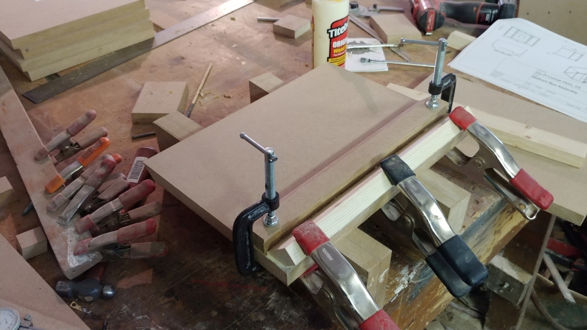 Note the severe angle of the spring clamps. This angle has to be steep enough to force the glue joint to close at the feathered edge. The guide prevents any slippage. Note the severe angle of the spring clamps. This angle has to be steep enough to force the glue joint to close at the feathered edge. The guide prevents any slippage.
Once the glue dried, I ripped the 45degree angle on the back edge. After carefully squaring the miter gauge (a good time to get really fussy), I trimmed all the sides to length.
Next, I carefully marked out the inside width of the box on the top and bottom using the trammel. I used the sides to mark out their lengths, and glued pine corner braces in place.
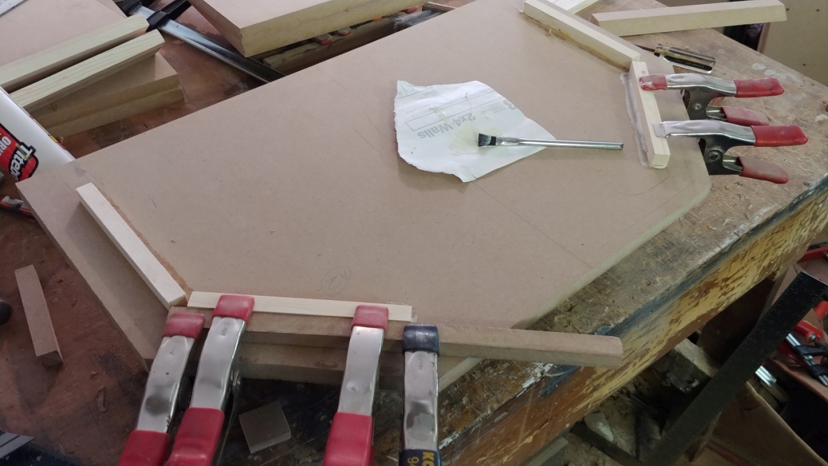
note the scrap clamped along the layout lines. This ensure the pencil line is not lost when the glue squeezes out over it.
I clamped a fence to the drill press table, and drilled the holes for the miter joint screws
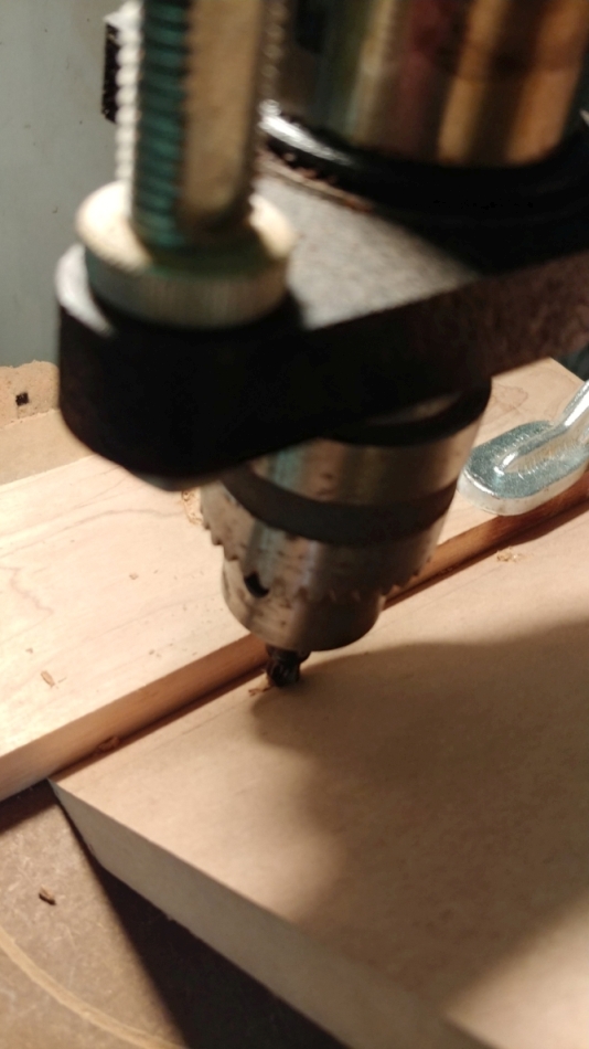
I did not pre-drill the sides for the threaded portion. Instead it assembled and disassembled the parts repeatedly while cleaning up the holes with a counter sink between each assembly. You will not be able to tighten these little screws enough to crush the parts together, so it is important that it get cleaned up well.
It was immediately apparent during dry assembling the box, that it would take too much time for Tight Bond glue, so I opted for old fashioned Elmer's White Glue.
I chamfered the edges of the sides where they meet the braces. Not doing this might prevent the sides from drawing up to the bracing if any residual glue remains.
I began the assembly by gluing the miter. I tightened the screws just enough to begin cloing the joint, but not enough to make it rigid.
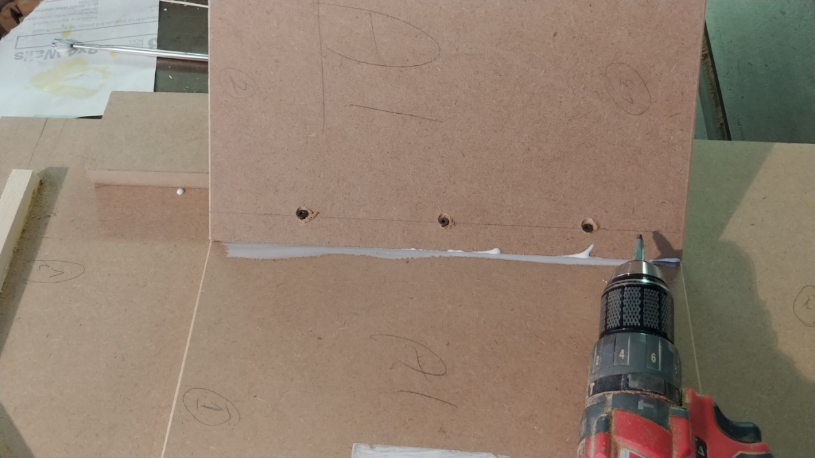
I then put the sides on, followed by the top.
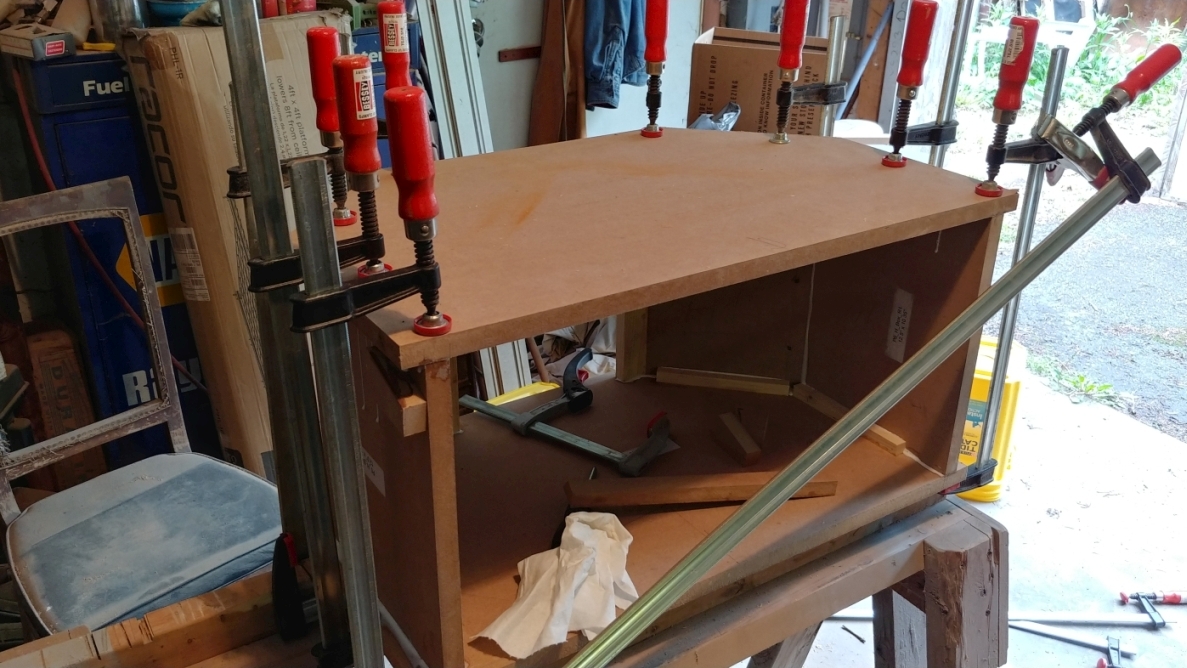
Clamping order is important here. I flushed all the front edges and lightly clamped vertically just at the front. I then clamped the cross wise to pull the side panels up against the braces. Next, I tightened the screws at the miter to draw that shut, and added a vertical clamp over the miter. I only have one clamp large enough to draw the rear side up to the braces that is still light enough to not be unwieldy. So I used this clamp with a piece of scrap to pull the rear sides up to the braces, followed by a vertical clamp to hold it in place. The horizontal clamp is then removed since it will draw the box out of square. Lastly, I measured corner to corner and clamped diagonally to square up the mouth of the box. The mouth needs to be as square as possible. Mine only required a little bit of coercion to square it up.
Next, More midhorn building 
|
|
|
|
| Re: Build Thread: 2Pi Towers, 6Pi Corner horns (and possibly a sub and center) [message #88436 is a reply to message #88057] |
Sat, 14 July 2018 15:09   |
 joshua43214
Messages: 35
Registered: October 2016
Location: USA
|
Baron |
|
|
I trimmed the extra material off the horn flares, and sanded the joints flush.
The flare was then inverted over the mouth of the box, and the long edges marked out for trimming
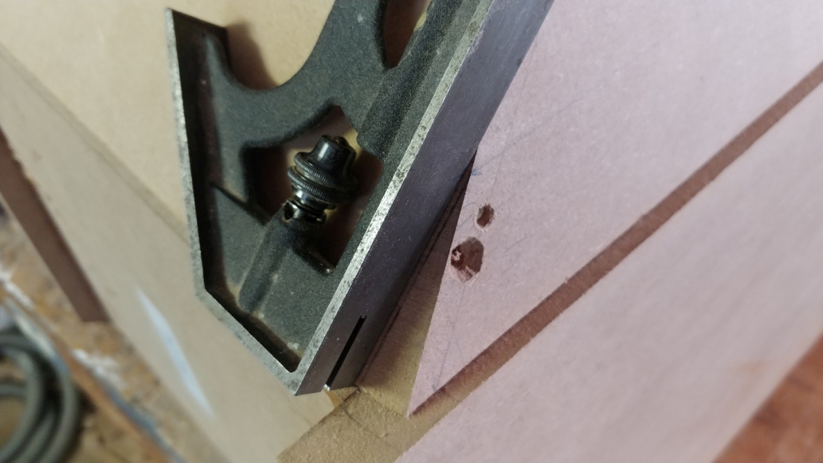
I used one of the supports for the bass bin as a sled to run the flare through the table saw. I first made a cut that I was sure would be ok, then tapped the fence over as much as I dared and cut to the line.
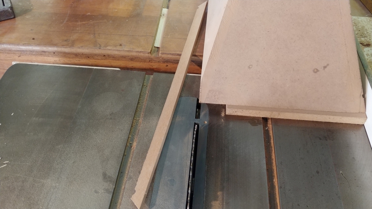
Fitting the long edge is just a matter of sanding until it fits, while being extra careful to sand to the line, and to keep the edges parallel.
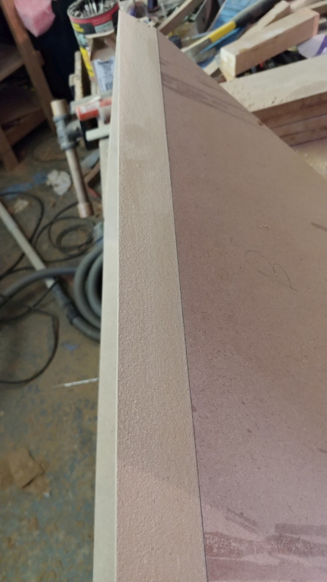
Once the flare is close to fitting, extra care should be taken to not split the box. MDF is a very weak material in tension, and you will split it with almost no effort. Patience is the key, it does not take any special talent or skill. Just check it often, wear a glove, and think happy thoughts.
The human eye is remarkably adept at spotting regular shapes and shadow lines. Measure over and over as you go to make sure the top and bottom edges are the same width, and they are not tapered.
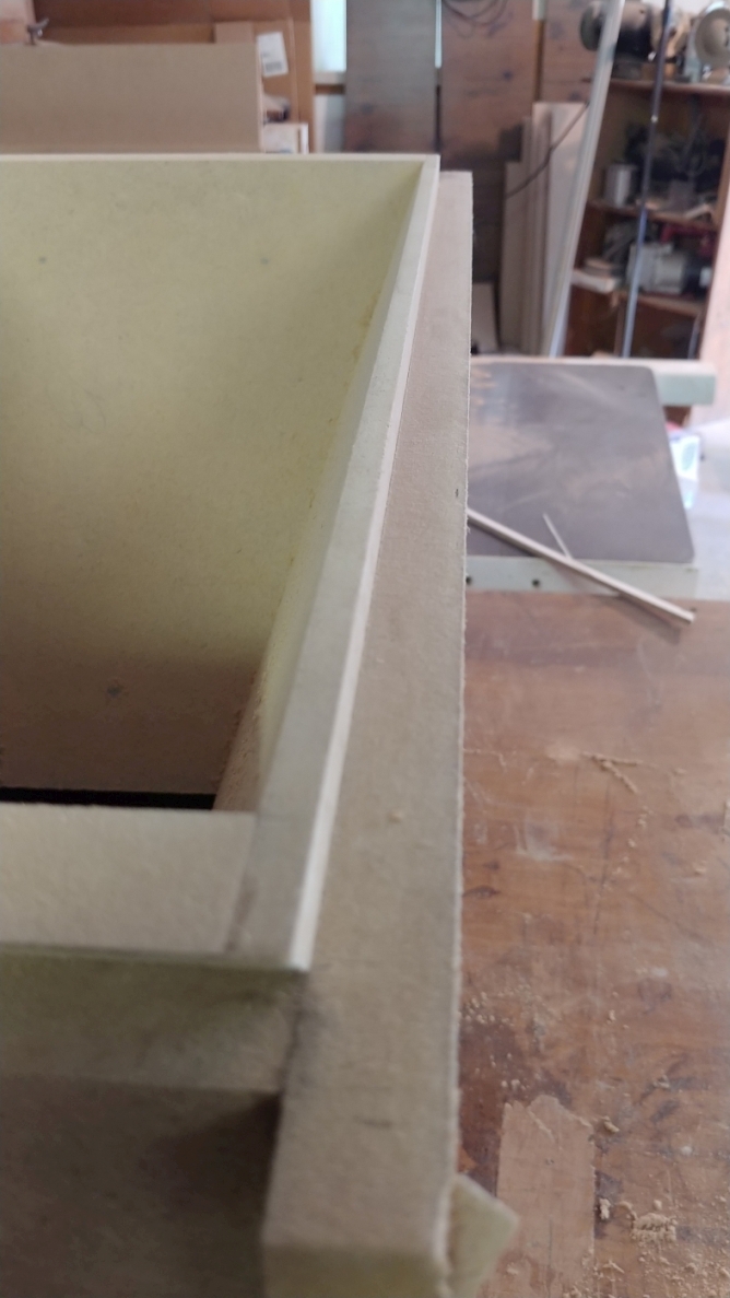
Trust your eyes. If it looks like this when you sight down the edge, you have done very well.
Next: Finishing up the flare
|
|
|
|
| Re: Build Thread: 2Pi Towers, 6Pi Corner horns (and possibly a sub and center) [message #88437 is a reply to message #88057] |
Sat, 14 July 2018 16:12   |
 joshua43214
Messages: 35
Registered: October 2016
Location: USA
|
Baron |
|
|
Fitting the short edge is much the same as the long edge with a couple differences. Trimming of the bulk is not easily done on the table saw. I trimmed it off with a handsaw. unlike sanding blocks, handsaws to require a bit of skill to use well. Just stay inside your comfort zone and use whatever tool you feel most comfortable with.
Before I marked out the cut line, I spent some time fussing about getting the flare even in the box. I used a dial caliper and levered the flare with a chisel until I had less than 0.005" (.127mm) difference. All of my earlier fussing was so I could make this particular measurement well. If the box or the flare are not square and flush at the fronts, then getting this alignment will be difficult. The more out of alignment this is, the more the flare will be aimed off axis, and the more the driver will be out of vertical. How much does this really matter? Hardly any if there is only one speaker. The point is not that the horn and driver must be in some perfect plane, it is that the pair should be as identical as one can make them.
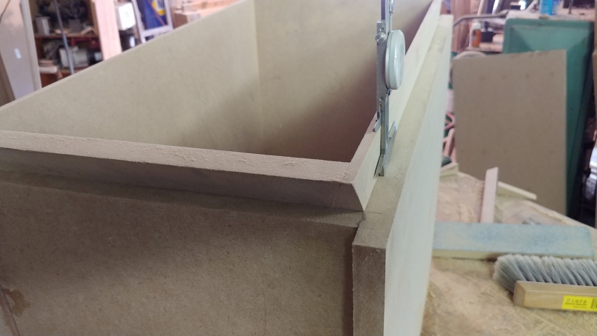
One again, just sand to the line, think happy thoughts, and check often. When fitted, the flare should fall in with minimal friction. Just enough to prevent it from free falling, but not so tight that it produces a starved glue joint.
This next image is actually out of order, but the operation can be done at this stage. Sorry, it is the hazard of writing a build thread after the project is completed.
I used a fly cutter on the mill to trim the throat of the horn flat. This can also be done using straight edges and rulers, which is the method I used for flattening the back of the box. Still it is a cool pic with a scary tool
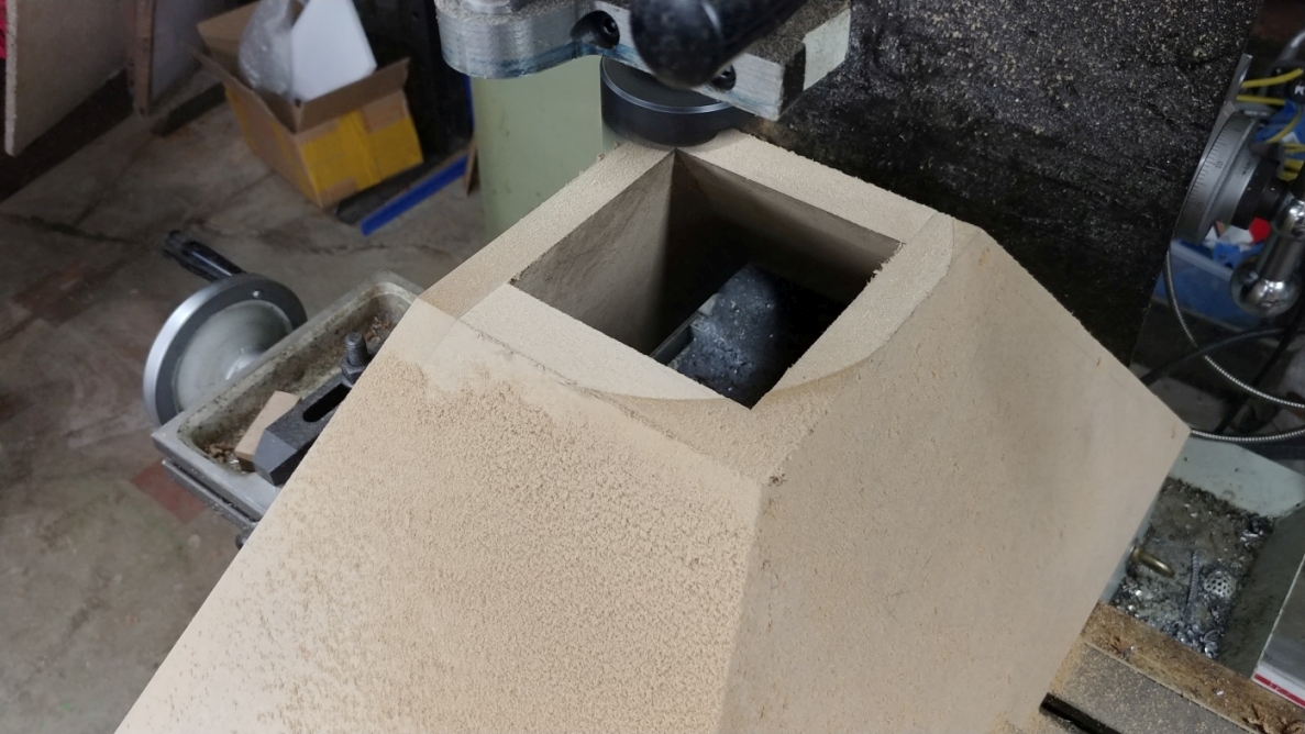
Once the flare was fitted. I glued it in place and used some spring clamps to keep the joint tight. It is important to work quickly doing this, Tight Bond grabs and starts to set very rapidly. Make sure you have a mallet and an assortment of scrap for beating the flare into place.
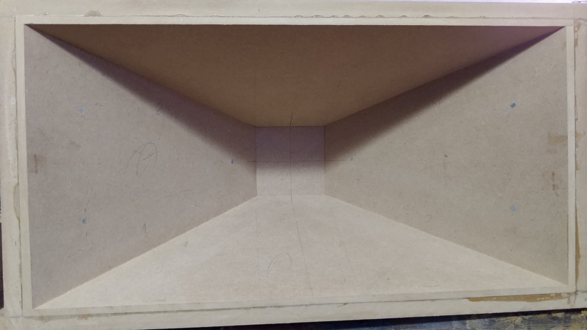
Before I glued the flare in place, I very carefully marked the center of each side of the throat. After assembly, I test fitted the driver support after marking out the center of it.
I think this is about as good as it gets, the driver support is less than 0.010" (.254mm) out of alignent, and that only on one edge. The other horn came out the same.
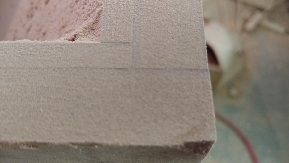
This is more or less how all 4 corners on both horns came out after flush sanding.
Next: Even more Horn work
|
|
|
|
Goto Forum:
Current Time: Sun Dec 21 03:21:22 CST 2025
|


