|
Home » Sponsored » Pi Speakers » H290C Horn/Waveguide (Upgrade for the obsolete Eminence H290)
| Re: H290C Horn/Waveguide [message #73258 is a reply to message #72816] |
Thu, 12 July 2012 08:08   |
 |
 Wayne Parham
Messages: 19000
Registered: January 2001
|
Illuminati (33rd Degree) |
|
|
Measurements
all measurements taken using DE250 driver
mounted on infinite baffle, i.e. half-space
drive signal 8.4v
microphone distance 3M
Impedance

The impedance graph shows first 1/4λ mode is around 800Hz, and 1/2λ about 1.6kHz. You can also see it in the response curve below.
All horns like this (conical, quadratic, oblate spheroidal) have a peak at the 1/4λ mode. The dimensions of the H290C place that peak just below the passband, which I find an attractive configuration.
Its pure oblate spheroidal flare profile sets its length and mouth size based on its tangential wall angle and throat size. These are fixed dimenisions, set by its geometry, as discussed earlier in this thread. A conical or OS flare has to be at least as long as half its width to achieve the right mouth size to support a 90° pattern. You can't create a right triangle with any other dimensions.
On-axis response
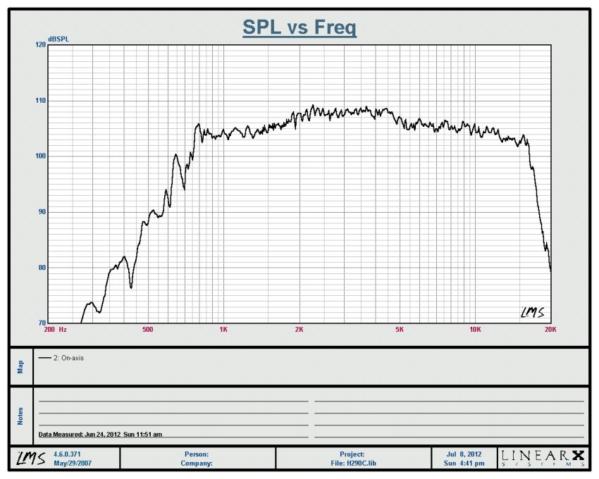
Devices like this have a peak at cutoff, followed by reduced output through the first octave. That's because they don't really provide good acoustic loading down low. They start becoming most efficient around 1/2λ and above.
That's why the π crossover provides a method for setting specific damping in the crossover region, as well as for setting the top-octave compensation for mass-rolloff. The values chosen for the π pad set the bottom-octave level (by virtue of crossover filter Q) and top-octave level (by virtue of attenuator bypass capacitor and/or shunt resistor and the rising impedance of the voice coil). So this very versatile crossover configuration is perfect for waveguides.
Horizontal Response Curves, every 10° through a 180° arc
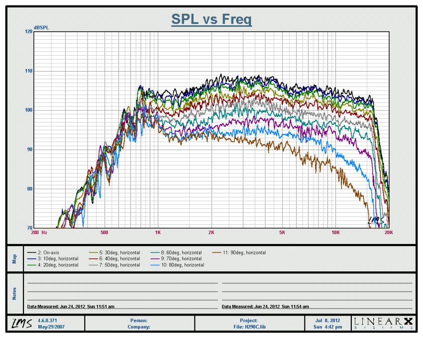
Horizontal off-axis response is excellent, very uniform through the coverage pattern, and well-behaved outside the pattern too.
Horizontal Contour Chart (Directivity Sonogram)
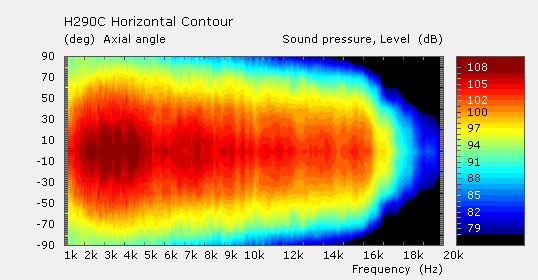
Viewing the horizontal beamwidth using a sonogram, you can see that energy distribution is very uniform. However, you may also notice that at low frequencies, the beamwidth doesn't widen as you might expect, it actually becomes more narrow. This is called waistbanding, a narrowing of the beam before the pattern widens at low frequencies below 1kHz.
The H290C waveguide is optimized to reduce internal reflections through the passband, and to do this requires the oblate spheroidal flare profile remain pure, without much of a secondary flare widening at the mouth. This approach trades a slight amount of waistbanding for reduced internal reflections, smoother response and improved overall sound quality.
This is a useful tradeoff because waveguide beamwidth narrows in the crossover overlap region where it blends with the other sound source. The two sources contribute to the overall summed response in all axes, and this provides the loudspeaker designer an easy solution path for uniform directivity.
The chart above shows the energy produced at all horizontal angles without normalization. Being denormalized, you see the actual energy distribution at various angles, not the directivity as referenced to the on-axis level. If we want to see that, we must normalize the curves to the on-axis chart, as shown below:
Horizontal Contour Chart (Normalized to the on-axis curve)
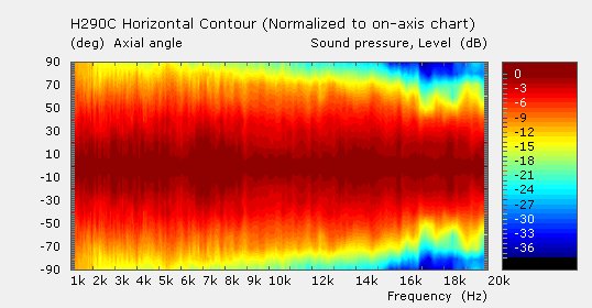
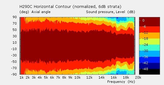
This shows directivity is constant through the passband. The definition of beamwidth is angles where the SPL is -6dB from the on-axis level, which can be seen to be constant at 90° (+/-45°).
It is easier to see the -6dB points if we stratify the contour gradient at 6dB rather than every 1dB. This shows the beamwidth angles very clearly:
Horizontal Contour Chart (Stratified at 6dB increments)
Now to the verticals.
Vertical Response Curves, every 10° through a 180° arc
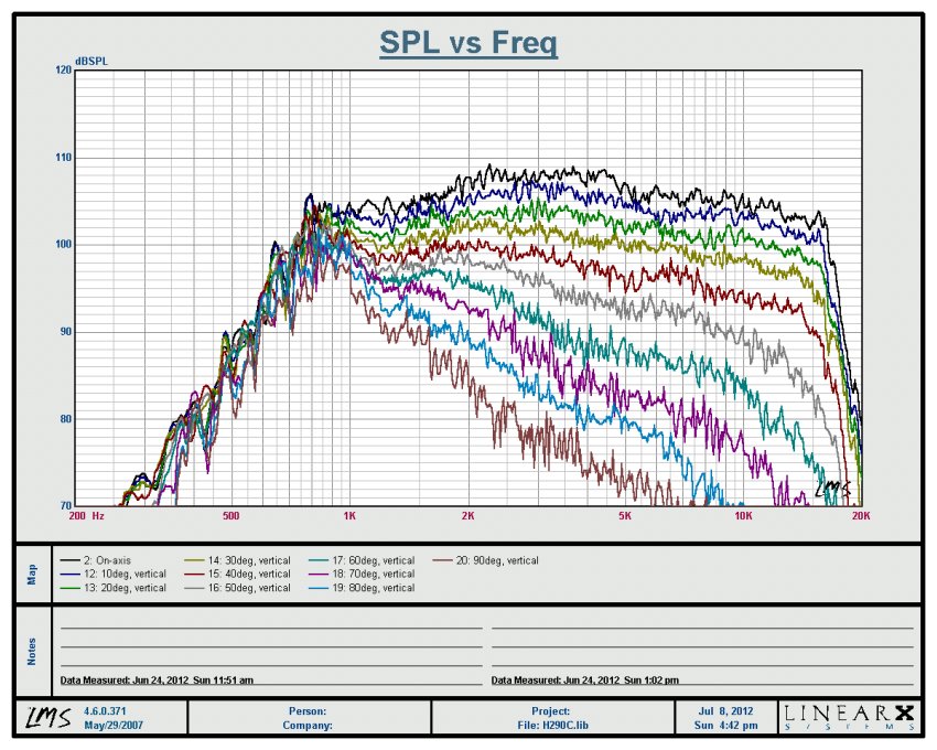
Naturally, the output at large off-axis angles is reduced considerably in the vertical. This is exactly what we want. It cannot maintain directivity control all the way down to 1kHz like it does in the horizontal axis - the horn is too small in the vertical dimension. But it is able to start gaining directivity control around 2kHz, which is excellent for a horn of this size. It also manages to collapse directivity gracefully, largely due to the mouth roundover and baffle mounting.
As you can see, directivity smoothly collapses as it begins to get control around 2kHz. By 3kHz, it is around 50°, and it remains pretty constant above that point.
Vertical Contour Chart (Directivity Sonogram)
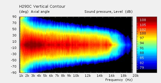
Again, we are viewing the energy produced at all vertical angles without normalization. Being denormalized, you see the actual energy distribution at various angles, not the directivity as referenced to the on-axis level. If we want to see that, we must normalize the curves to the on-axis chart:
Vertical Contour Chart (Normalized to the on-axis curve)
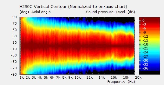
This shows vertical beamwidth is constant from 3kHz upwards through the passband. Again, the definition of beamwidth is angles where the SPL is -6dB from the on-axis level, which can be seen to be constant around 50° (+/-25°).
It is easier to see the -6dB points if we stratify the contour gradient at 6dB rather than every 1dB. This shows the beamwidth angles very clearly:
Vertical Contour Chart (Stratified at 6dB increments)
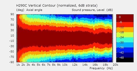
|
|
|
|
|
|
|
|
| Re: H290C Horn/Waveguide [message #73403 is a reply to message #73399] |
Sat, 28 July 2012 12:13   |
 |
 Wayne Parham
Messages: 19000
Registered: January 2001
|
Illuminati (33rd Degree) |
|
|
Thanks for the thumbs up, guys. I'm really proud of it.
As many of you know, but some probably don't, this H290C horn is a molded plastic implementation of a horn I developed about ten years ago. It's the horn shape I always wanted. For many years, I've used horns that were close, mostly because they were available and gave me 95% of what I wanted. But this is exactly the right shape, without compromise.
My first go at a no-compromise horn/waveguide was what I now call the H390C. I made it out of wood, and it is as much aesthetically beautiful as it is acoustically correct. The thing is, since it is designed to be cradle mounted, it doesn't have the benefit of the baffle, and therefore had to be made a little larger.
This H290C is the exact same shape as the H390C from throat to about 70% the length of the horn - It has the OSEC (oblate spheroidal / elliptic cylindrical) flare profile in both horizontal and vertical planes, and also in the transition at the edges between them. This shape allows the wavefront to transition perfectly from the plane wave generated by the compression driver into a section of a sphere at the mouth. This transition from plane wave to spherical wave is one of the most important functions of a horn/waveguide.
The biggest difference between the H290C and the H390C (besides material) is the radius to the mouth. The H290C doesn't need as much of a radius, particularly in the vertical. The baffle provides some assistance here, reducing the size requirements. That is a welcome feature, since reduced vertical size allows center-to-center spacing between sound sources to be made smaller, increasing the size of the forward lobe. That has always been important to me.
This horn has been a long time coming. It really is the latest evolution of three decades of work. There are other waveguides out there, some from relative new comers, others from experts in the field. But none of them are as good as this waveguide, in my opinion. This one is the exact right shape and size for what we're trying to do. It's the horn I always wanted.
|
|
|
|
|
|
| Re: H290C Horn/Waveguide [message #73411 is a reply to message #73410] |
Sun, 29 July 2012 10:40   |
 |
 Wayne Parham
Messages: 19000
Registered: January 2001
|
Illuminati (33rd Degree) |
|
|
Thanks for your kind words. If you're interested, some of the history is described in the following links:
As for the development of the H290C in particular, I had initially been attracted to the quadratic throat waveguide, as it resembled radial horns which I had empirically found to provide the best performance. Then later, after discussing oblate spheroidal waveguide/horns with Earl Geddes, and then upon finding the documents below about Gaussian wave propogation, as well as many other texts on similarly related topics, I was convinced this flare profile made sense.
Conoidal surfaces are defined by lines drawn tangent to an oblate shperoid. The resulting curve is a hyperboloid of one sheet whose asymptotes pass through the origin (x/y axis) inclined at an angle cos-1 with the z axis.
You will notice on page 73 of the first paper above, equation 4.2 is the formula used to plot this flare profile, the one commonly referred to as describing an oblate spheroidal (and/or elliptic cylindrical) waveguide/horn. It forms a hyperbola created from a line drawn tangent to an oblate spheroid or elliptic cylinder. The two are the same profile, but the OS is round while the EC is rectangular. The two can be joined easily, since they are based on the same family of elliptic coordinate systems, allowing for a smooth transition between round throat and rectangular mouth of whatever aspect ratio is desired.
I have also used a polynomial expression to plot this flare profile, one that tracks the trigometric function precisely, but it is a more complex formula. I did it purely as a curve fitting exercise.
These are the equations used to describe the H290C waveguide/horn:

What is not shown by these formulas are the mouth radius and the profile at the edges.
The mouth radius is borrowed from LeCleach, in that it is a gradually increasing angle calculated using an iterative approach. But it is not a large part of the total profile so in truth, it could have been a tractrix or some other shape, even an arbitrary radius. I just wanted to avoid any sharp edges.
Similarly, I wanted to provide smooth features on the diagonals, but also to maintain as much of the area as possible, which is why I chose a rectangular profile. I think the super-ellipse would have been fine too, but I saw no reason to take that shape, so what I did was to use the same formula as shown above and apply it for the oblique angles, but just enough to provide a round entrance that gradually blends the sides with top and bottom so that the exit is rectangular.
The end result is a shape that has slightly wider tangential angles on the diagonals. The profile starts off round, then slowly changes to elliptical, then towards more of a super-ellipse, then finally to a rectangular exit. But the profile at every point - horizontal, vertical or obliques - is described by the trigonometric formula above.
My design goals were to create a device that had uniform directivity but not at the expense of response smoothness. I also wanted an asymmetrical flare, because I like the ability to minimize the vertical spacing of MF and HF sound sources.
I always though that discontinuities inside the horn caused response ripple due to impedance spikes. They also cause diffraction, which may be useful for widening the pattern but it destroys imaging. So waveguides are attractive in that they limit these problems, but many of them aren't so good at acoustic loading, and so suffer from response ripple. I wanted the best of both worlds, and I found that it is possible, provided you design the waveguide paying attention not only to flare profile but also area expansion and length.
The asymmetrical flare prevents ceiling slap at high frequency, which I find very useful. It also allows close vertical spacing, which then provides a nice, tall clean forward lobe. And it has a side benefit, which is that it doesn't have a huge on-axis dip from mouth reflection like round horns do. I wouldn't want the loudest radiation angle to have a lot of ripple, and asymmetrical mouth mitigates this. So the vertical nulls are widely spaced, and there is no on-axis null. I find that much more attractive than having large nulls on-axis, as well as slightly above and below the speaker, like round horns have.
I've heard it said that the oblique radiation from a elliptical or rectangular waveguide is abnormally wide. This is true. But I find this to be completely acceptable, especially in light of the fact that this very feature makes the forward lobe so nice and tall. I think it is weird to look at the obliques, when the verticals are more important. Fix those first. Nulls out at oblique angles are usually pretty fuzzy, and I just don't see a problem there.
I've also heard it said that an asymmetrical horn has less vertical pattern control, or that it gains control only at higher frequency, the so-called pattern flip thing sets in. This is also true. But what I tend to see in most of these ~90°x50° waveguides is that they haven't "flipped" at the ~1kHz crossover region, they're basically doing 90°x90° there. The horizontal is in control, and vertical isn't yet, it is still collapsing up for another octave or so. The vertical nulls are usually around +/-25° if the speaker is well designed, so the forward lobe is clean, about 50° tall. Within the next octave or so, the horn gains vertical control and limits beamwidth to 50° for the rest of the range. So I think that's a pretty good paradigm.
Another thing that is attractive is the asymetrical mouth shape allows the area exapansion to be less than what it would be from a asymmetrical flare having the same horizontal angle. This is useful for acoustic loading. This is the best waveguide shape for my loudspeakers, and in my opinion, is the best waveguide shape for any speaker that is to be used for home hifi. It gives the smoothest response possible, low diffraction and well-behaved uniform directivity.
|
|
|
|
|
|
|
|
|
|
|
|
Goto Forum:
Current Time: Wed Feb 04 06:44:33 CST 2026
|


