|
Home » Audio » Group Build » Art Array Improved Crossover
| Art Array Improved Crossover [message #32207] |
Mon, 09 February 2009 10:23  |
 FredT
FredT
Messages: 704
Registered: May 2009
|
Illuminati (1st Degree) |
|
|
Over on the Parts Express Tech Talk forum Pete Schumacher has developed an improved crossover for the Art Array. This new crossover solves some problems of the original crossover that are discussed in the thread. Page down for the new crossover schematic.
|
|
|
|
| Re: Art Array Improved Crossover [message #32208 is a reply to message #32207] |
Mon, 09 February 2009 13:03   |
 |
 Wayne Parham
Messages: 19001
Registered: January 2001
|
Illuminati (33rd Degree) |
|
|
Thanks for the link, Fred.A few thoughts: The measurements that were made weren't close mic'ed, they were done at two meters, if I recall. I would have preferred a little more distance, but I was working in an area where I couldn't really throw the power at them so I wanted to be sure and be above the noise floor. I chose a power/distance that seemed to be the best compromise. Also, perhaps more importantly, the measurements weren't done with the speakers on their sides. They were measured outdoors, standing upright with the microphone on axis with the tweeter. See the thread about ART Array measurements. I think you might be thinking about the fact that I did lay them on their sides and measure them to get a comparison, to see the effects of ground reflecton mitigation from the array. I never published that dataset, but I am certain I commented about it, probably privately in an E-mail. I often comment on how vertical arrays smooth floor bounce, much in the same way that multi-subs smooth room modes. The Vifa tweeter does benefit from a damping resistor, but I don't see a huge peak in acoustic output near its resonance. It works very well with a simple first-order filter and small amount of resistor damping. Of course, reducing excursion in turn reduces IMD. Then again, there are advantages offered by first-order filters too.I remember thinking it might be good to attenuate that hump with compensation in the woofer circuit. The trouble is, the hump is just below crossover so if you do it by overdamping the low-pass filter or simply shifting the crossover frequency down, then the Vifa tweeter would have to be used at lower frequency too. I don't think that's a good idea. You could use a notch filter, but that has never been an approach I particularly liked doing. In the end, I personally thought it was best to leave it simple. It sounds good.Don't forget that unsmoothed LMS measurements are brutal. Lots of people are not used to seeing them. Most speakers measure far worse than your arrays did. Reducing the 700Hz hump would be possibly worth doing, but the rest of the curve is pretty good. Other than possibly smoothing the 700Hz hump, I would not expect to improve amplitude response by any significant amount with a crossover change. One thing is for certain. Measurements will tell you if a crossover change is an improvement or if it is just different. I think it is worthwhile to try the notch filter to see if it helps, but I would not feel confident calling it an improvement until I had measured it to see. I would also want to do it under the same conditions, because just 1/3rd octave smoothing would make the response curve of your speakers look very smooth. So be careful to compare apples to apples as you proceed. Start with a new baseline for comparison on whatever measurement platform you choose. Measure the stock crossovers, then compare proposed changes with the same measurements system, environment and settings. Good luck and keep us posted!
|
|
|
|
|
|
| Re: Art Array Improved Crossover [message #32210 is a reply to message #32209] |
Mon, 09 February 2009 14:38   |
 |
 Wayne Parham
Messages: 19001
Registered: January 2001
|
Illuminati (33rd Degree) |
|
|
I do all my initial designs by modeling, and I encourage others to do that too. I don't believe any optimizaton was done on the ART Arrays, so maybe it's time. But I think the only way to find an improvement is with real measurements. Your design is past the point of most DIY modeling efforts.Sophisticated models would be required to get past where you are, or better yet, obtaining real data from measurements of actual samples. One suggestion is to use the Smith & Larson WTPro measurement system, which fuses Spice modeling and acoustic measurements into an extremely powerful development tool. That's what I use for development work, and I use LMS for measuring finished products. Again, the main thing I would focus on is the hump at 700Hz. That may be reduced a little bit. But really, the response chart for the stock speaker is pretty good. At no point does the amplitude response vary more than +/-5dB in the passband. Average (3rd octave smoothed) response is within +/- 3dB from 40Hz to 25kHz. That's not bad at all, so I don't expect huge improvements from a crossover update. Only subtle improvements could be made, at best. If the curve had been made for publication by a marketing department, they would have set the scale so it didn't show the peaks and valleys so well. It would have also been smoothed to 1/3 octave resolution. That's what people are used to seeing, and your speaker by comparison would have looked very good. I didn't post the chart that way, because I like seeing the detail. Trouble is, that makes it seem worse than it is I suppose. If the chart had been "bad" I would have suggested some changes when you first presented the speakers to me for measurement. Not only was it "not bad" but I think it was pretty good, especially for an entry-level DIY speaker using relatively inexpensive parts. The tweeter is fine with the first-order HP filter. I have literally thousands in the field in one π and two π speakers and I haven't had a single failure. That tweeter circuit is exactly the same as what you've used in the ART Array. Perhaps a different slope might be employed for phase/summing, but then again, measurements showed first/first summed better than second/first. From that, I'm guessing this speaker probably responds best to symmetrical or nearly symmetrical slopes. The woofer circuit might be modified a smidge, maybe changing the LP filter, inserting a notch filter or modifying the Zobel. That might help reduce the 700Hz hump. On the other hand, the speaker with first-order LP filter measured better than the second-order, with less attenuation on the top end, not more. That tells me probably you want these particular midwoofers to run up just about as high as they can, just shaving any breakup modes from the top. In the end, you may find that this issue is specific to the woofer chosen, and that anything you do to correct its rise at 700Hz changes the response elsewhere, perhaps doing more harm than it does good. Can your ART Array be improved, probably. Does it need to be? That's harder to say. Average response from 40Hz to 25kHz within +/- 3dB is pretty good, in my opinion. But if optimizations are found that bring it even flatter, say to within +/-1.5dB, that's even better. I'm interested to see, so please let us know how things progress. If there is a genuine improvement found, we'd like to post it in the Projects directory with the original plans and schematics.
|
|
|
|
| Re: Art Array Crossover - Further Evaluation [message #32211 is a reply to message #32210] |
Sat, 14 February 2009 23:26   |
 |
 Wayne Parham
Messages: 19001
Registered: January 2001
|
Illuminati (33rd Degree) |
|
|
Fred Thompson linked to a thread on another forum, where there has been discussion about his ART Array design and some proposed changes to it.
I spent some time making responses over on that thread, but found a little too much vitriol over there for my tastes. That's one of the reasons I rarely post in forums outside of ART. So I'll post here instead.
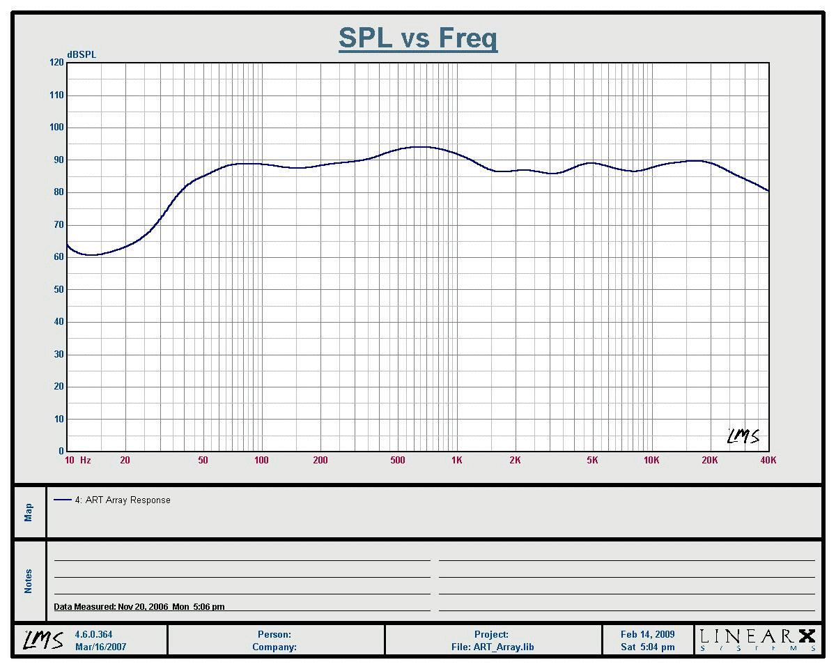
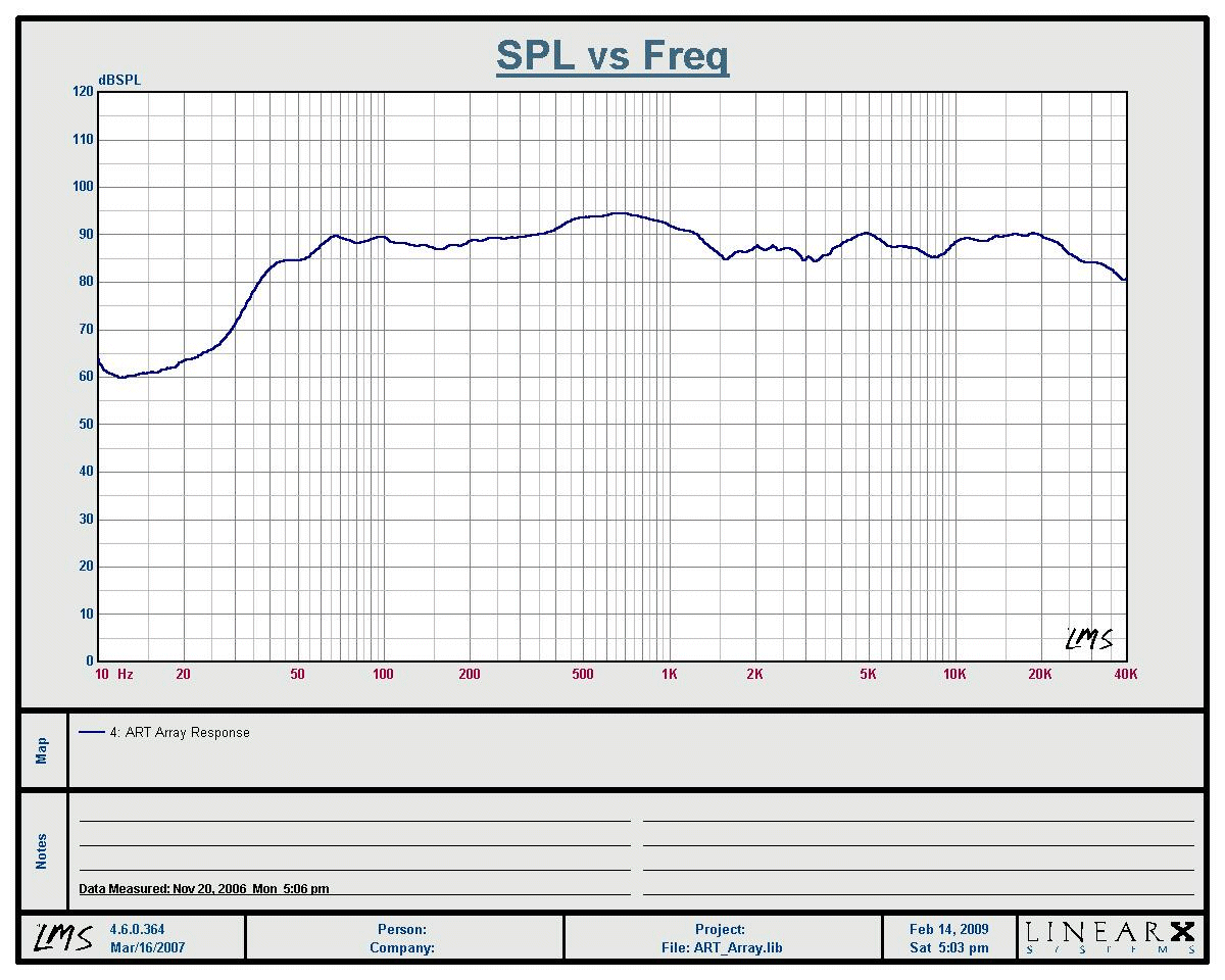
The original response chart posted for the ART Arrays was an unsmoothed chart, scaled to show detail very clearly. This kind of chart is very unflattering, and if people aren't used to seeing charts like this, they can easily misinterpret the data. It does look rough, but any speaker you measure at that high resolution will look somewhat rough. So I've dusted off the old datasets of the ART Arrays and reposted them in two other ways, one that is scaled 10dB/division and another that is 10dB/division and smoothed to 1/3rd octave resolution. This is the way most are accustomed to seeing the data, since most marketing materials and published response charts are done this way.
 ART Array Response, 1/3rd Octave
I said in the PE thread that the 1/3rd octave chart was within +/-3dB from 40Hz - 25kHz and that's not completely accurate. I was shooting from the hip when saying that. The actual figures are closer to 55Hz - 25kHz, +/-3dB. Still a very good response chart.
The unsmoothed response chart is shown below. When shown in higher resolution, some detail becomes clear that shows small valleys in the passband that dip below -3dB from the average level. The hump at 700Hz can be seen to rise above +3dB also. This is not unusual, many speakers have these kinds of features that show up in response in an unsmoothed chart.
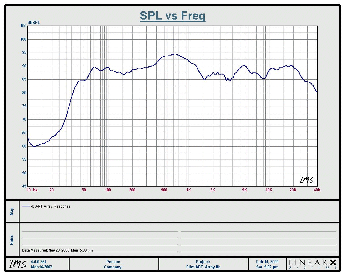
One thing that is different between this chart and the original one posted a couple years ago is that it is scaled to 10dB per division rather than 5dB per division. Scaling makes a visible difference in that peaks and valleys don't seem so large.
 ART Array Response
I measured the ART Arrays a couple years ago, and looked at them in several ways. I did not publish all of the data I captured, not even close, but I did get a pretty good understanding of what they are capable of. One of the things I noticed was that they were fairly insensitive to placement, that changes in boundary conditions didn't change the response much. Another thing I noticed was as long as you were more than a few feet back, response was pretty uniform with the microphone within about 30° from being straightforward from the tweeter. I didn't get out the protractor to measure polars, but I did notice that the boom could be moved around quite a bit and still get fundamentally the same chart.
This was with the crossover having symmetrical slopes for woofer and tweeter. I also measured a crossover having different slopes for woofer and tweeter, and it did not sum properly in any plane. The woofer array and tweeter are all mounted on the same baffle, so this makes sense. In a way, the tweeter becomes a part of the array in the overlap band.
I would expect that crossovers with higher order filters on the tweeter might work OK at very close distances straight on axis with the tweeter. If the measurement microphone is very close to the loudspeaker and straight on axis with the tweeter, then it is further from the woofer array. The added delay from a higher-order HP filter on the tweeter would make summing right in this special case where the listener is abnormally close to the tweeter. However, at normal listening distances, the listener will be approximately the same distance from the tweeter as the woofer array, certainly to the inner woofers. That's why crossovers with symmetrical slope provide the best summing.
The original response curve I posted was unsmoothed and the plot is scaled to show a lot of detail.
 ART Array Response
It is possible that the 700Hz hump could be reduced with a notch filter or an overdamped LP filter on the woofers. However, the hump is immediately below the crossover frequency, which makes it difficult to use an overdamped LP filter without reducing the effective crossover frequency. An overdamped filter will make the woofers rolloff too soon.
A crossover can be easily developed with an overdamped low-pass circuit or lower crossover frequency. The problem is, that makes it necessary to lower the HP frequency for the tweeter too. If the slope of the tweeter is made higher, it will reduce stop-band energy, so a balance may be made between crossover frequency and slope. It might be possible to find a set of values that satisfies all these conditions, but it is a non-trivial problem because there are competing priorities.
In the final analysis, I think the simple first-order crossover is one of the better choices for this loudspeaker, if not the best choice. I would not have guessed that when I first looked at the speaker. I would have guessed a higher-order crossover would have been better. But the first-order crossover is simple, the measurements look good and it sounds good too.
|
|
|
|
|
|
| Hmmmmm [message #32213 is a reply to message #32207] |
Fri, 06 March 2009 19:36   |
 Shane
Shane
Messages: 1117
Registered: May 2009
|
Illuminati (3rd Degree) |
|
|
|
Well I posted on the PE forum with a few simple questions. Mainly if the new xover would affect the sensitivity of the speakers. Pete responded that it won't. I won't get into arguements about xover design because I have no idea how they work. His xover design may be the cat's meow, who knows till it's in the speakers. I'm happy with the 1st order xover I have now, but if someone is willing to buy me parts I'll build one of Pete's designs and we'll just see what it sounds like  I don't care how many sims you run and on what software. Just because something sims out, or even measures great, doesn't mean it will sound good. Look at SET amps. They tend to measure crappy compared to SS or PP. But a great many of them sound very nice. If it doesn't sound good in the end then it's just junk to me.
|
|
|
|
| Re: Hmmmmm [message #32214 is a reply to message #32213] |
Tue, 10 March 2009 17:44   |
 |
 Wayne Parham
Messages: 19001
Registered: January 2001
|
Illuminati (33rd Degree) |
|
|
Passive equalization works by attenuating certain portions of the response curve. So it will reduce output in certain areas. Pete wanted to reduce the octave around 700Hz by a couple decibels, but nowhere else. I don't see any harm in doing that. So all in all, the average sensitivity would be pretty much unchanged.
The issue for me is whether or not it merits doing. The performance of the speaker with first-order crossover is good, in my opinion. I'm not sure I would want passive equalization in the crossover. If I were going to consider it, I would definitely want to measure polars, not just equalize the on-axis curve flat. Whether modeling or measuring, if you focus only on what happens on-axis, you're overlooking the bigger picture which is the total energy put into the room.
The sound in the room is a reverberent field, and the spectral balance is set by the power response, not the on-axis response. The kinds of circuits that taylor on-axis response almost always do that at the expense of power response, because of the collapsing directivity inherent in all loudspeakers not designed specifically for constant directivity.
I think it's interesting to look at these two design philosophies. I know smart guys that design each way. Some guys use BSC regularly, and compensate for on-axis response. Others prefer to design the system for flat power response, which generally uses a different compensation scheme. Neither is more right than the other, in my opinion, but one embraces the reverberent field and the other tends to ignore it.
|
|
|
|
|
|
|
|
Goto Forum:
Current Time: Mon Feb 09 15:50:25 CST 2026
|


