|
Home » Sponsored » Pi Speakers » Compact version of 6Pi / 7Pi (Choosing between 6Pi and 7Pi and wife compatible modifications)
| Re: Compact version of 6Pi / 7Pi [message #99722 is a reply to message #98714] |
Sat, 22 August 2026 05:55   |
 Henner
Messages: 9
Registered: January 2024
Location: Sydney Australia
|
Esquire |
|
|
Dear Wayne,
After 2.5 years I am back on the wife-compatible 7Pi project. It is somewhat sad how little time I have for my hobbies.
The design has matured. I would like to get your final thoughts / recommendations / blessing on the changes made before I create manufacturing files out of it. Once all is good, do you mind if I make these plans publicly available?
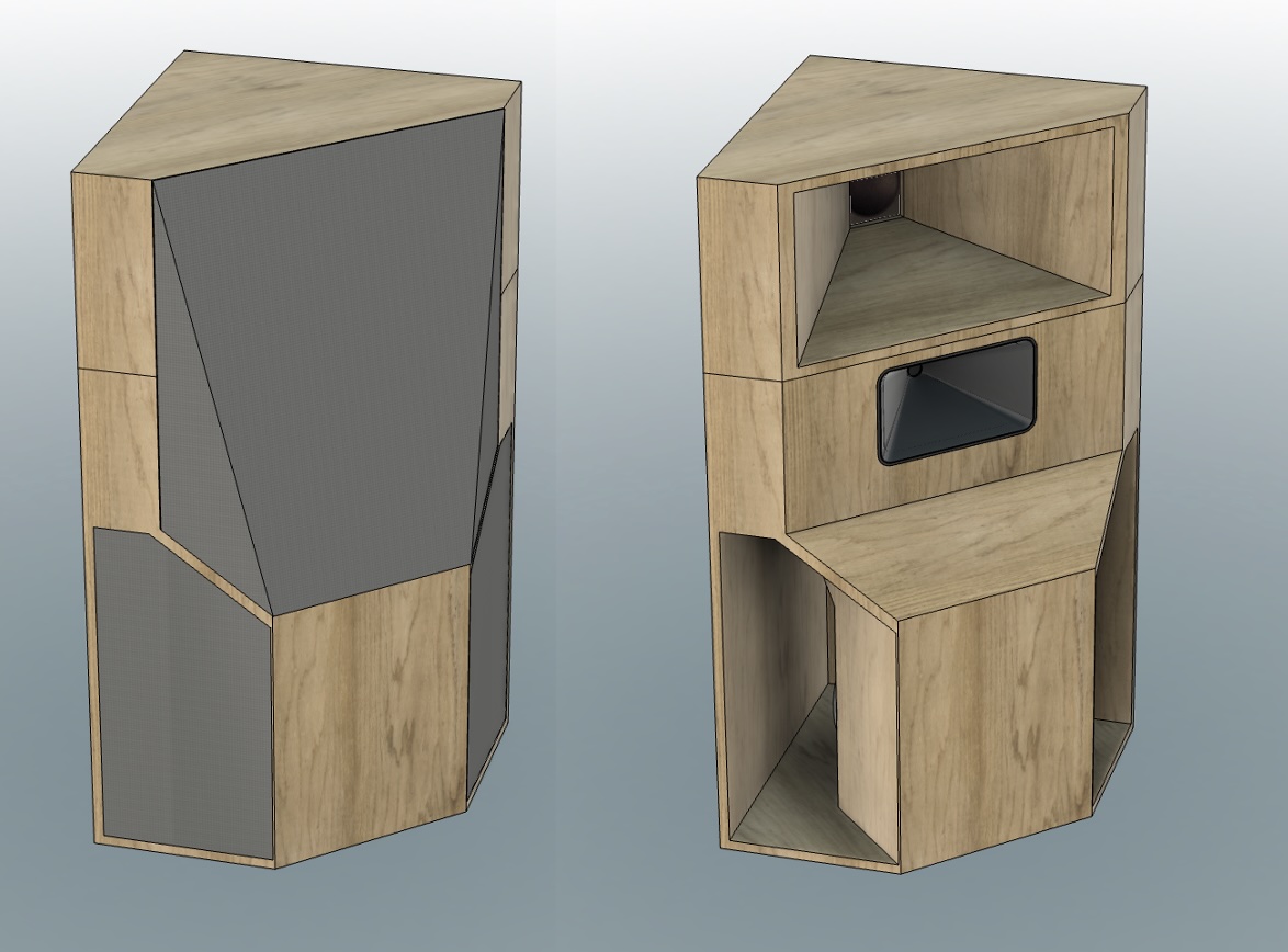
What I kept is the general layout idea of maximum compactness and using all available volume.
Changes:
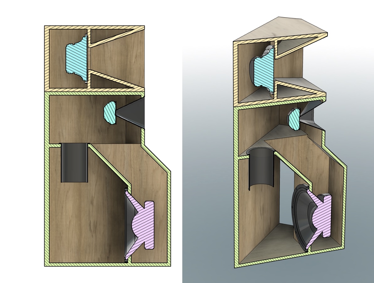
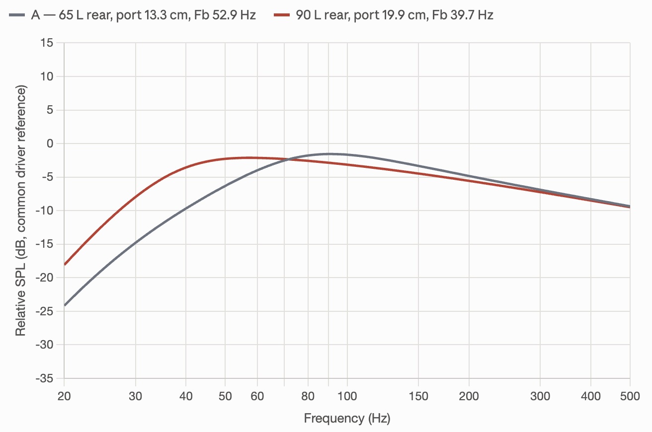
- The bass chamber and tuning frequency have changed from your original 65L with Fb 53Hz to a 90L chamber with Fb 40Hz. More on this later in this post.
- I kept all joint angles at 90 and 45 degrees for easy CNC routing.
- The "apex chamber" of the base was decreased from your original 154L to 72L.
- The opening area of that "apex chamber", let's call it the throat, was reduced from the original 2700 cm² to 1500 cm².
- Added an option for slanted acoustic fabric to avoid the look of a rear-projection TV — I am sure my wife will choose a fabric with a decorative print, such as cherry blossom.
- Overall height and floor space slightly reduced from your original: 4" shorter and 1.5" less from the room's corner to the front.
- I tried to keep the acoustic centres of the drivers as close to your original as possible, as I wanted to avoid making any changes to your crossover.
The changes to the bass chamber resulted from simulation. My objectives were reducing the amplitude hump of the published frequency response by 1.3dB and also achieving maximum bass extension. A point of diminishing returns was reached at a 90L chamber with a tuning of Fb 40Hz (F3 32Hz, F6 28Hz). A lower tuning was not possible without creating a hump caused by corner gain that was impossible to mitigate by simple volume and port tuning. I believe that this is the optimum of what can be achieved with this driver, cabinet and corner combination.
I am fully aware that a multi-sub installation would greatly reduce the room modes, room gain and modal ringing below the Schroeder frequency — which is around 200 Hz for my room. I thank you for having explained this so well in your fantastic essays. Unfortunately, separate subs are not feasible due to space and wife acceptance, thus maximum bass extension and mitigating the room's response with DSP. Given the high efficiency, I believe that I can quite comfortably extend the response into the lower 30Hz region, even with a small 25W First Watt F5, or a small SET amplifier.
The port area of 142cm² is unchanged, thus air velocity remains the same. The length has increased to 20cm though. This reduced the pipe port resonance from your original 1kHz to 547Hz. It is still well above the 250Hz crossover frequency and I can use flared ports to smear out the resonance peak, but not as good as your 1kHz. If you think that is insufficient and I should rather increase the port velocity (reduce cross section), please let me know.
A word on the simulation:
The bass section was modeled as a standard Thiele-Small 4th-order vented box: the JBL 2226H (published parameters: fs 40 Hz, Qts 0.31, Vas 175 L) in the rear chamber, tuned by the internal port (142 cm²), with enclosure losses set to QL = 7. The front chamber (apex chamber) is deliberately not modeled as a lumped bandpass volume, for two reasons that the numbers support: first, its Helmholtz/quarter-wave mode (103 Hz in the original 154 L chamber) is critically damped by corner radiation loading — radiating into 1/8-space at the wall apex raises the mouth radiation resistance roughly 4×, dropping the mode Q to ≈1.7, so no peak forms; second, the chamber dimensions exceed λ/8 above ~50–80 Hz, so it acts as a waveguide redirecting the driver to the corner rather than as a compliance. A full lumped two-chamber model was tried and rejected because it predicts features the published measurement does not show.
A calibration was needed though. Two smooth empirical terms were then fitted against the 7Pi response from your webpage: a corner-loading gain shelf, 9/(1+(f/38)³) dB, representing the 1/8-space boundary reinforcement, and a high-frequency tilt, −(3.2/4)·log₂(1+(f/65)⁴) dB, representing the woofer's declining top end together with the 250 Hz mid-horn overlap. With these, the simulated original should match the published curve to 0.51 dB RMS from 20–250 Hz. If you want to reproduce this in WinISD/VituixCAD/Unibox: simulate the vented rear chamber with QL = 7, export to a spreadsheet, and add the two dB terms (or refit them by subtracting your own baseline simulation from the digitized factory curve). But note that this is for this particular corner setup and not valid for other speaker placements.
Let me know know what you think. 
|
|
|
|
Current Time: Thu Oct 22 15:17:37 CDT 2026
|


 Posting Rules
 Members
 Search
 Help
Help Register
 Login
Login Get a T-Shirt!