|
Home » Sponsored » Pi Speakers » Pi Crossover Boards and Biamping
| Re: Pi Crossover Boards and Biamping [message #76137 is a reply to message #76132] |
Tue, 02 April 2013 10:48   |
 |
 Wayne Parham
Messages: 19000
Registered: January 2001
|
Illuminati (33rd Degree) |
|
|
The connectors on the π crossover PCB are just 0.205" spade lugs for printed circuit boards. You can get them at any electronics supplier, Digikey, Newark or Mouser, for example. Do a search for "PCB Quick-Fit Male Terminal 0.205" and you'll find plenty of them. They're all designed to be mounted on pads with plate-through holes but I bend over the hole tabs because I want one side of the board to be completely flat for mounting purposes.
If you are thinking about biamping, you don't really need the π crossover PCB. Of course, it's nice to have the passive crossover, because it is fully optimized and provides a baseline. It allows the speaker to be used with a single amplifier too. But a biamp configuration is possible, of course, and would negate the need for a passive crossover.
I tend to warn people that they'll need to do some work to setup an active crossover, and not to think that they will enjoy improvements just by simply having one. It requires a crossover/processor that can be programmed to provide any transfer function, not just one that allows the user to select a set crossover frequency and slope. And it takes a little bit of time with an acoustic measurement system, to optimize the system at all off-axis angles. The process is shown in my "Crossover Optimization" thread. The basic process is described, and there is a link to a video that shows you how to find the vertical nulls, which mark the edges of the forward lobe.
The low-pass filter for the woofer is pretty straightforward, but the tweeter circuit is a little more complex. And of course, proper on-axis and off-axis summing through the crossover region requires careful selection of both high-pass and low-pass sections, both in terms of frequency and phase. This is usually set by slope and filter type, and sometimes standard types aren't even used.
The damping of the waveguide's high-pass filter circuit must be adjustable as well as the slope and frequency, because we set the lower "shelf" by setting filter Q. In most cases, it is slightly underdamped because (properly sized) conical horns and waveguides tend to rolloff a little down low. On the other hand, truncated conical horns and waveguides tend to have a peak down low, and in this case, the tweeter circuit can be overdamped to partially compensate. This is a very important feature of the π pad in the passive crossover - It provides a way to adjust the region just above crossover and to tailor it for any waveguide. You will need to provide this in an active crossover as well.
Most people tend to think an active crossover can be easily configured using "CD compensation" but I find this is rarely the case because of the lack of filter Q adjustability. The 6dB/octave compensation for mass-rolloff is the easy part, it's just a single pole RC or RL filter. That's what "CD equalization" in most active crossovers provides. But the result is a transfer function that's a diagonal line, and that doesn't work well in most cases.
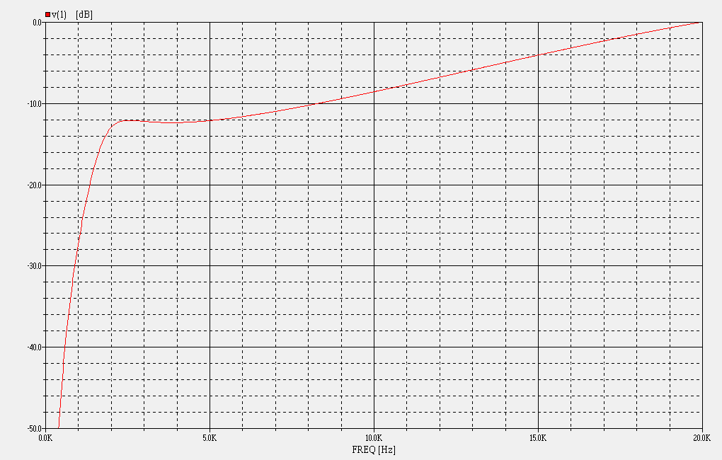
Mass rolloff doesn't start to occur until around 4kHz, so we usually want flat response up to that point, followed by 6dB/octave rising response. And as I said above, each individual waveguide has its own unique charasteristics in the ~1kHz octave too, some needing a little more damping, some a little less. So for the active crossover to be useful, it needs to capable of adjusting the transfer function of the tweeter circuit accordingly, usually something like this:
 π crossover tweeter circuit transfer function
|
|
|
|
Current Time: Wed Feb 04 10:29:32 CST 2026
|


