|
Home » Sponsored » Pi Speakers » Compact version of 6Pi / 7Pi (Choosing between 6Pi and 7Pi and wife compatible modifications)
| Compact version of 6Pi / 7Pi [message #98714] |
Sat, 21 June 2025 07:38  |
 Henner
Messages: 7
Registered: January 2024
Location: Sydney Australia
|
Esquire |
|
|
Dear Wayne,
Thank you for your great service to the DIY community!
For me, the holy grail are low-distortion constant directivity corner-horns for all the reasons you've already explained very well. Matured designs are very rare to find, and yours are by far one of, if not the best!
I have a few questions regarding the 6/7Pi, as well as modifications.
1) I'm trying to decide between the 6Pi and the 7Pi, each configured with the best drivers you have as options. My current listening room is relatively small at 20m². In the future we plan to move, but I don't expect a room larger than 40m². I primarily listen at low to medium volume levels. My main power amp is a 25W FirstWatt F5.
Which one do you recommend, the 6Pi or 7Pi? And what's the reason for your recommendation?
2) Most of us have partners with low tolerance for large speakers in the living room—so does my wife. Her aesthetic requirements are fairly basic though. It has to be relatively low in height and square in shape, at least square when covered by acoustic fabric. In addition, she'd like to put things on top of it, possibly even a similar-sized shelf.
As I like keeping my wife happy and I'm also an engineer, I thought I'd try to modify the 6/7Pi to make them wife-compatible. I started this a couple of years ago, then my work got busier and the project stopped. Today I have a free day and here I am. Back then I asked Wayne some basic questions on modification and he gave me the OK as long as I keep the internal volumes the same. I've gotten a little further since then and have more questions. I thought I'd post this in the forum as others might find it useful.
My first questions focus on the bass horn of the 6/7Pi.
The 1st image shows the 6/7Pi. The 2nd and 3rd images show the original bass horn and its floor print. In blue is the reflex chamber. The 4th and 5th images show the modified bass horn with floor print. Again, the reflex chamber in blue. I followed the edge of the wall to create a square. This extended the cross-section of the reflex chamber (blue) by 25%. This allowed me to lower the height of the bass horn by 25% while keeping the chamber volume unchanged. Good—wife is 25% happier.
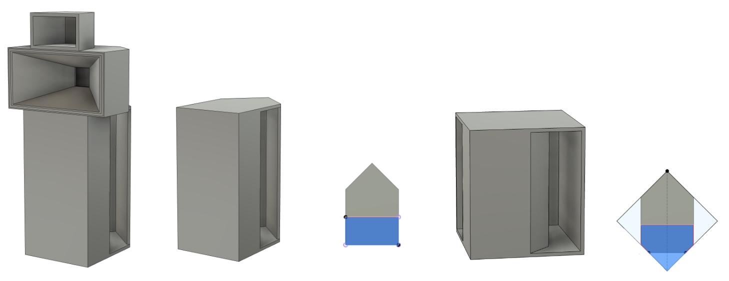
2a) My first question relates to the opening of the mouth of the bass horn. Now it is 25% shorter, thus 25% smaller in cross section. The width and all other angles remained the same. Will that affect the frequency response in a noticeable way? If yes, should I adjust the mouth's width, or do I have to revert back to the original height?
2b) The front of the bass chamber changed from flat to pointed. Will that make any notable difference to the frequency response? I assume not, but I thought I'd ask to be sure.
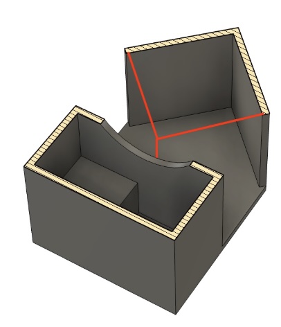
2c) I noticed that the section between the driver and the horn's mouth (the section that sits in the room's corner) is not increasing consistently towards the mouth. It appears to be a front chamber rather than just an expanding horn. I indicated in red what I would have expected the section to look like. Was this "front chamber" intended for acoustic reasons, or was it a design simplification to make things easier for the person who builds the enclosure? If it was for acoustic reasons, what does the "front chamber" do? I ask because I failed to simulate it with Hornresp.
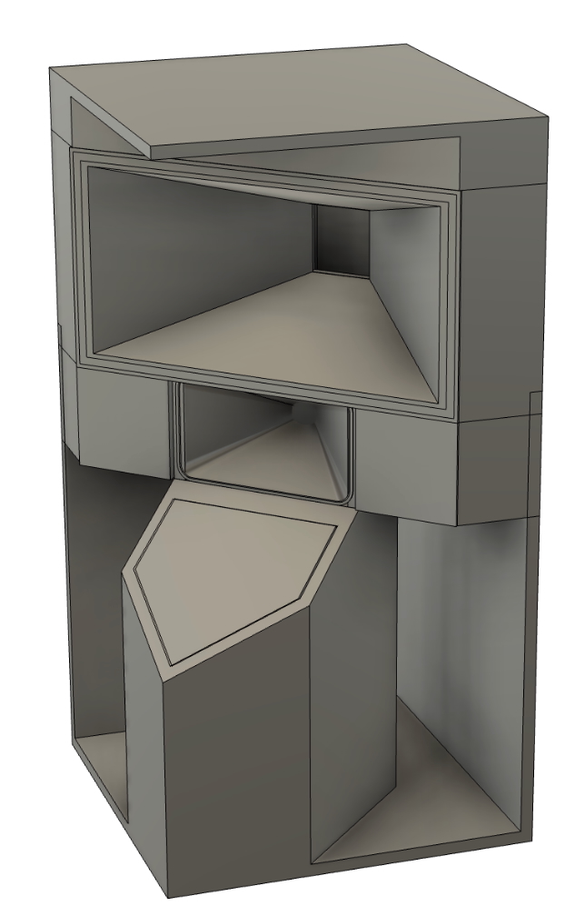
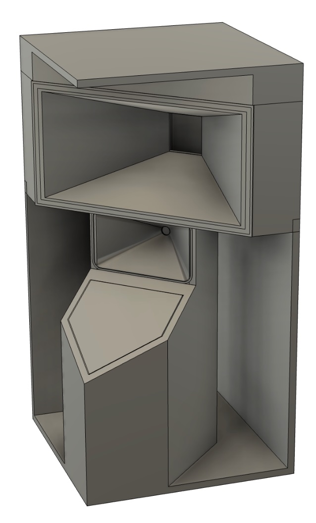
2d) I made two variations of the 6/7Pi that have the compression driver positioned between the mid-horn (top) and the bass horn (bottom).
(I am aware that the compression driver is best positioned at the ear level of the listener. Yes, I might run into trouble with furniture between a sitting listener and the horn.)
Kindly tell me which of the following versions would be preferable and why.
Version A allows the unused volume around the compression driver to be added to the reflex chamber of the bass horn. That would allow a potential further reduction in overall height by keeping the reflex chamber's volume unchanged. However, the mouth of the bass horn and the mid-horn would be separated by 16cm. This affects the overlapping vertical radiation lobes of course. Would that be noticeable?
Version B sacrifices the previously added volume to the reflex chamber (from the unused volume around the compression driver) to allow for more mouth height of the bass horn. Thus eliminating the previously described separation between the mid-horn and bass horn.
3) If I were able to scale up your compression horn to the size of the mid-horn and use that instead of the one with flat sides as in your drawings, would that give any advantages?
To the members of the forum: Once I refine the design a little more, and Wayne gives his OK, I can make the CAD file available for everyone to use. 
-
 Attachment: VersionB.jpg
(Size: 88.38KB, Downloaded 868 times)
-
Attachment: VersionA.jpg
(Size: 169.45KB, Downloaded 843 times)
-
Attachment: 2c.jpg
(Size: 35.77KB, Downloaded 873 times)
-
Attachment: image 1-5.jpg
(Size: 63.54KB, Downloaded 881 times)
|
|
|
|
| Re: Compact version of 6Pi / 7Pi [message #98716 is a reply to message #98714] |
Sat, 21 June 2025 10:47  |
 |
Wayne Parham
Messages: 19083
Registered: January 2001
|
Illuminati (33rd Degree) |
|
|
That's really cool! I really like the appearance of your design.
And as we've discussed - and you've elaborated upon here - the bass bin in my constant-directivity cornerhorns is not particularly sensitive to dimensional changes. It doesn't run very high in frequency, so we don't have the potential standing wave problems that we might if bandwidth were wider.
The bass bin alone is really a very simple device. Its whole significance is being acoustically close to the apex of the corner. It uses no compression and really doesn't have a front chamber. It has a "rear chamber" but that's really just a slightly overdamped vented cabinet.
All we are getting from this design is a sound source that's acoustically close to the apex of the corner, so the walls act as "vertical ground planes" rather than reflectors. And having those walls be vertical ground planes forces the radiation to be quarter-space and directed into the room.
To clarify, it does have a "front chamber," as you've observed. But it's acoustically insignificant. A front chamber in most horns provides a little bit (or sometimes a lot) of low-pass. It doesn't do that in my design. It's more just a positioning device - the whole bass bin is essentially just that.
As for the rest of your design - I love it. Looks really cool!
Choose your woofer and bass bin tuning based on whether you like the Italian B&C 12PLB100 or the American JBL 2226H. That's really the only difference between the six Pi and the seven Pi models.
I think the only one other thing I might add is your comments about extending the waveguide. I think that's what you were saying when you talked about "scaling up the compression horn to the size of the midhorn," yes?
The H290C waveguide really benefits from baffle-mounting. It helps it reduce waistbanding, which is the narrowing of the radiation angle at the bottom end of its passband. So your version A drawing would help there.
The midhorn and tweeter waveguide are more tightly coupled than the bass bin and the midhorn. What I mean by that is the crossover between midhorn and tweeter keeps their forward lobe phased properly so their vertical nulls are located symmetrically above and below, approximately matching the horn flare angle.
The midhorn and bass bin overlap in the upper modal region, between about 100Hz and 200Hz. The midhorn goes as deep as it'll run, and the bass bin has a slow, shallow first-order low-pass. The whole ideas is sort of like what is done with flanking subs, in that the sound sources are interacting with the room in its modal region.
I say "sort of like flanking subs" because of the blending aspect. Also, flanking subs do mitigate higher frequency room modes. But they are primarily used to mitigate SBIR, which is caused by reflections from nearest boundaries. The worst offender is usually the wall behind the speakers.
They smooth higher frequency room modes by adding more sound sources, similar to multisubs but used higher in frequency. Those higher frequency modes are usually worst from the first-order vertical axial mode, but also include higher-order modes and tangential and oblique modes.
In constant-directivity cornerhorns, higher-frequency vertical room modes are mitigated by the overlap of the midhorn with the bass bin. So we aren't expecting them to provide radiation that would result in clean verticals in free space. Quite the opposite. They aren't in free space. We are expecting to add more vertical sources in the overlapping region to mitigate the vertical axial modes, which occur higher in frequency than the other axial modes.
The horizontal axial modes are the ones that cause low frequency problems, and you'll want to incorporate multisubs to mitigate those. You can put a pair of subs in the opposite corners, or elsewhere in the room, far from the mains. They'll give extra extension and low-frequency modal smoothing.
|
|
|
|
|
|
| Re: Compact version of 6Pi / 7Pi [message #98720 is a reply to message #98718] |
Sun, 22 June 2025 09:44 |
|
Wayne Parham
Messages: 19083
Registered: January 2001
|
Illuminati (33rd Degree) |
|
|
The H290C can be made with an additional roundover at the mouth to reduce wastebanding without the use of a baffle. That's what the H390C is - essentially an H290C made out of wood with additional mouth roundover for free-space operation, set upon a cradle-mounted stand.
But the problem is that this also changes geometeries and distances between sound sources. That usually necessitates a crossover change to get the forward lobe right, and that in turn requires a measurement - test / modify / retest - design cycle. So unless you are wanting to go through that, I'd stick with what you've done in version A.
Beyond that, I'll respond to your questions below.
1) I can change the front "chamber" to what I indicated in red under point 2c without significantly affecting the sound.
I didn't fully understand what chamber shape you were planning to make, but I can say that it isn't critical so I do not expect any problems. I'm assuming your shape is still pretty "open and free" so any low-pass properties are minimal. You'd almost have to create a bandpass chamber - limiting the opening to a small duct - to cause yourself a problem here.
2) The height / cross section of the bass-bin's mouth can be reduced without noticeable difference in frequency response.
This is sort of like the first question, in that you could make fairly large changes without causing a problem. The bass bin is really just a positioning device, placing the woofer near to the apex of the corner, and the slots are just a result of that. I found them somewhat empirically. The goal was to have the woofer acoustically near the walls but not so close that the slots formed a compression chamber.
3) The H290C requires baffle mounting, meaning that Design B is not suitable.
That's right, although I wouldn't say it isn't suitable. The H290C can be operated in freespace, but having a baffle reduces waistbanding. So I would suggest that version A is probably preferable.
4) Separating the mid-horn and the mouth of the bass-horn by 16cm is acceptable, thus Design A is OK.
That's totally fine. We're overlapping and blending the midhorn and bass bin sound sources in the upper modal region to help smooth vertical modes. By shifting the vertical position of the sources, you're really shifting the vertical modes of those sources. But you're still blending them and they're still in the same acoustic scale. You've only shifted by six inches, not six feet. So the region affected is still in the same range, which is the upper modal region.
5) Both the B&C 12PLB100 and the JBL 2226H are equally suitable for very low-level listening.
Both are excellent woofers. Both are excellent for low-level listening and both are excellent for fairly high power levels too. Low distortion, smooth response.
|
|
|
|
|
|
|
|
| Re: Compact version of 6Pi / 7Pi [message #98807 is a reply to message #98806] |
Sat, 09 August 2025 23:33 |
|
Wayne Parham
Messages: 19083
Registered: January 2001
|
Illuminati (33rd Degree) |
|
|
So glad you got the 2226H drivers! They are awesome!
The original seven Pi cabinet actually used a slightly larger wood horn, which had additional mouth radiusing to combat waistbanding.
The H290C isn't too bad in this regard, as you can see in the measurements:
Still, it benefits from the baffle on the three Pi and four Pi speakers, which reduces waistbanding without the additional mouth radiusing. It would be even better if radiused and mounted on a baffle, but the trade-off is that the extra radiusing increases vertical distance between sound sources, bringing the vertical nulls closer together.
Personally, I would rather have the waistbanding than the vertical nulls too close together. But I digress.
In your case, you have a design that adds a little extra baffling where the tweeter will mount. None in the vertical, so I'm not sure how much it will help in the vertical plane but I suspect it will help a little in the horizontal. So that's why I would do it if I were contemplating your mods.
|
|
|
|
|
|
|
|
| Re: Compact version of 6Pi / 7Pi [message #99722 is a reply to message #98714] |
Sat, 22 August 2026 05:55 |
Henner
Messages: 7
Registered: January 2024
Location: Sydney Australia
|
Esquire |
|
|
Dear Wayne,
After 2.5 years I am back on the wife-compatible 7Pi project. It is somewhat sad how little time I have for my hobbies.
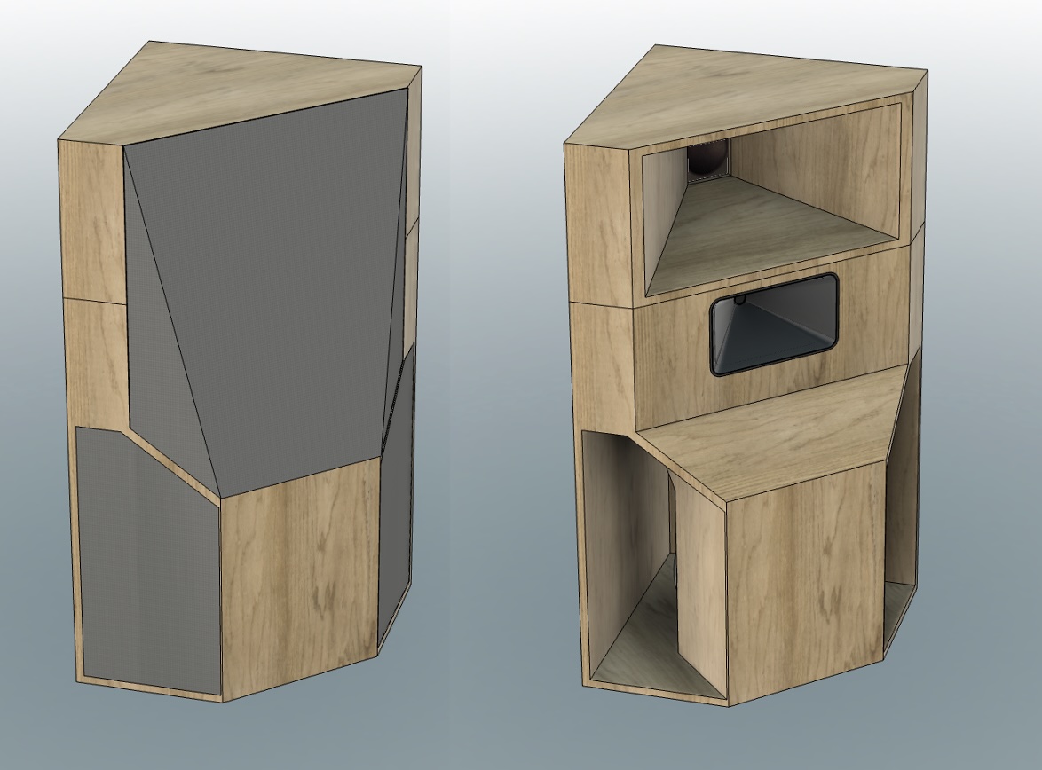
The design has matured. I would like to get your final thoughts / recommendations / blessing on the changes made before I create manufacturing files out of it. Once all is good, do you mind if I make these plans publicly available?
What I kept is the general layout idea of maximum compactness and using all available volume.
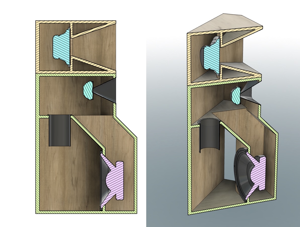
Changes:
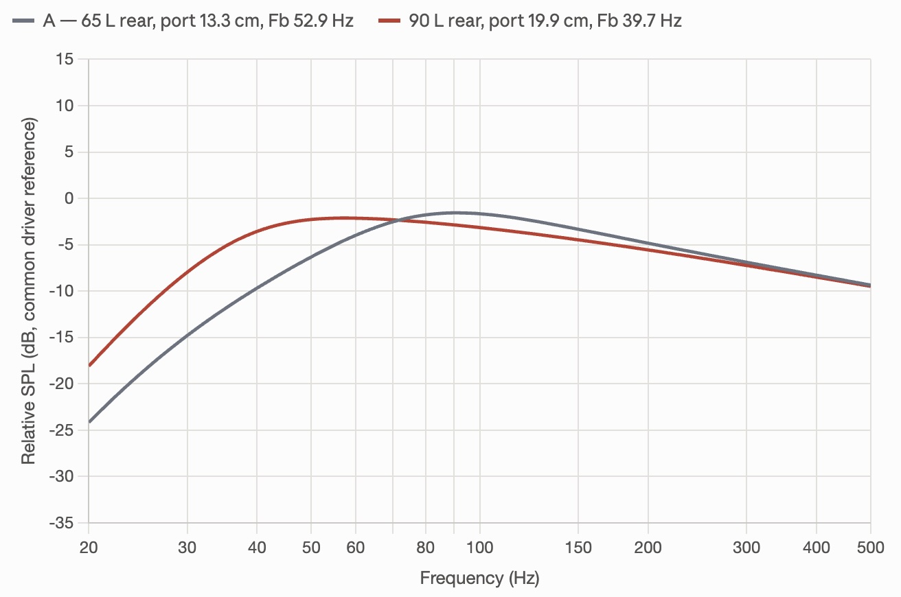
- The bass chamber and tuning frequency have changed from your original 65L with Fb 53Hz to a 90L chamber with Fb 40Hz. More on this later in this post.
- I kept all joint angles at 90 and 45 degrees for easy CNC routing.
- The "apex chamber" of the base was decreased from your original 154L to 72L.
- The opening area of that "apex chamber", let's call it the throat, was reduced from the original 2700 cm² to 1500 cm².
- Added an option for slanted acoustic fabric to avoid the look of a rear-projection TV — I am sure my wife will choose a fabric with a decorative print, such as cherry blossom.
- Overall height and floor space slightly reduced from your original: 4" shorter and 1.5" less from the room's corner to the front.
- I tried to keep the acoustic centres of the drivers as close to your original as possible, as I wanted to avoid making any changes to your crossover.
The changes to the bass chamber resulted from simulation. My objectives were reducing the amplitude hump of the published frequency response by 1.3dB and also achieving maximum bass extension. A point of diminishing returns was reached at a 90L chamber with a tuning of Fb 40Hz (F3 32Hz, F6 28Hz). A lower tuning was not possible without creating a hump caused by corner gain that was impossible to mitigate by simple volume and port tuning. I believe that this is the optimum of what can be achieved with this driver, cabinet and corner combination.
I am fully aware that a multi-sub installation would greatly reduce the room modes, room gain and modal ringing below the Schroeder frequency — which is around 200 Hz for my room. I thank you for having explained this so well in your fantastic essays. Unfortunately, separate subs are not feasible due to space and wife acceptance, thus maximum bass extension and mitigating the room's response with DSP. Given the high efficiency, I believe that I can quite comfortably extend the response into the lower 30Hz region, even with a small 25W First Watt F5, or a small SET amplifier.
The port area of 142cm² is unchanged, thus air velocity remains the same. The length has increased to 20cm though. This reduced the pipe port resonance from your original 1kHz to 547Hz. It is still well above the 250Hz crossover frequency and I can use flared ports to smear out the resonance peak, but not as good as your 1kHz. If you think that is insufficient and I should rather increase the port velocity (reduce cross section), please let me know.
A word on the simulation:
The bass section was modeled as a standard Thiele-Small 4th-order vented box: the JBL 2226H (published parameters: fs 40 Hz, Qts 0.31, Vas 175 L) in the rear chamber, tuned by the internal port (142 cm²), with enclosure losses set to QL = 7. The front chamber (apex chamber) is deliberately not modeled as a lumped bandpass volume, for two reasons that the numbers support: first, its Helmholtz/quarter-wave mode (103 Hz in the original 154 L chamber) is critically damped by corner radiation loading — radiating into 1/8-space at the wall apex raises the mouth radiation resistance roughly 4×, dropping the mode Q to ≈1.7, so no peak forms; second, the chamber dimensions exceed λ/8 above ~50–80 Hz, so it acts as a waveguide redirecting the driver to the corner rather than as a compliance. A full lumped two-chamber model was tried and rejected because it predicts features the published measurement does not show.
A calibration was needed though. Two smooth empirical terms were then fitted against the 7Pi response from your webpage: a corner-loading gain shelf, 9/(1+(f/38)³) dB, representing the 1/8-space boundary reinforcement, and a high-frequency tilt, −(3.2/4)·log₂(1+(f/65)⁴) dB, representing the woofer's declining top end together with the 250 Hz mid-horn overlap. With these, the simulated original should match the published curve to 0.51 dB RMS from 20–250 Hz. If you want to reproduce this in WinISD/VituixCAD/Unibox: simulate the vented rear chamber with QL = 7, export to a spreadsheet, and add the two dB terms (or refit them by subtracting your own baseline simulation from the digitized factory curve). But note that this is for this particular corner setup and not valid for other speaker placements.
Let me know know what you think.
|
|
|
|
Goto Forum:
Current Time: Sat Aug 22 17:04:46 CDT 2026
|



 Posting Rules
 Members
 Search
 Help
Help Register
 Login
Login Get a T-Shirt!