|
Home » Audio » Group Build » RIAA preamp project
| RIAA preamp project [message #67165] |
Fri, 22 April 2011 11:26  |
 FL152
FL152
Messages: 29
Registered: April 2011
|
Chancellor |
|
|
It started six years ago on this forum, with some talk about RIAA preamps, and I offered an idea of simple, two E188CC tubes based, direct coupled design. Passive RC RIAA filter between the gain stages. Well, nobody built it, including me, years went bye, and besides some experiments with similar D3a / C3g design, I almost forgot it. And yes, I was out of the forums for the last five years.
It restarted this Christmas, when Santa brought me the new Rega RP-1 turntable. Its Ortofon OM-5E MM cartridge puts 4 mV output on 47 k / 200-600 pF load. The sensitivity of my 300B SET is 1,2 Vrms / 25 kOhms, and that means some requiments for the RIAA preamp:
-amplification 300 times on 1 kHz (~50 dB)
-input capacitance isn`t too critical, but better to be on the lower side, ~200 pF
-low output impedance, < 1 kOhms, to drive about 3 m of cables and 25 k power amp input
And I put some additional requiements:
-low RIAA error, <0,5 dB
-simple, direct, good sounding, polarity (phase) non-inverting, two tubes per channel design
-large overload margin on all frequencies (~35 dB, by M. Jones)
-use of the „normal" parts, that I have or can easily obtain
-compact design, stand alone unit that can „drive" power amp to the full output
When I searched my parts collection I actually found everything I need - enclosure from salvaged `50s cinema console amplifier, two DN2540N5 based CCS modules I built for some other project and forgot about it, two MJE350/BC558/LED CCS modules I built years ago too, some quality NOS ERO KP1836 capacitors, even one multi- secondary small toroid PT I used for experiments, four noval teflon sockets...plus many other parts.
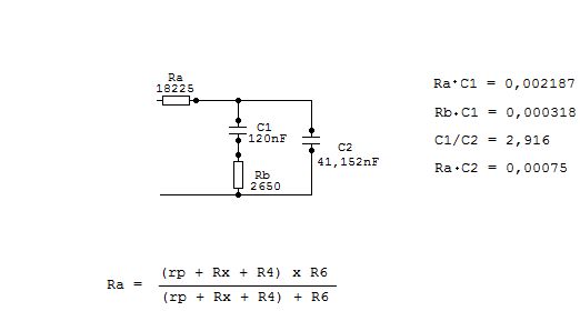
A quick calculation I made on the back of an envelope gave me the RIAA filter values. This time I decided to use low impedance version, smaller Rs, and bigger Cs. This is arranged with the parts I actually have, but can be easily changed for different RC values with formulas and schematic of passive RIAA filter.
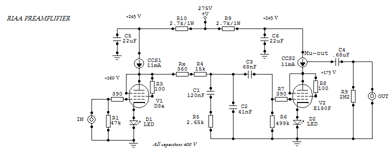
Here`s the complete schematic, one channel shown:
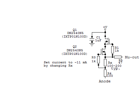
And there`s a CCS schematic, known from old projects:
Actually, Ra consists of a series Rout from the first tube (D3a in triode), R4=15 k and Rx in series, in parallel with Rg=R6 from 2nd stage, trioded E180F. We must know the Rout~rp value of D3a, and a little experiment is in the order. I measured the amplification of the first stage alone, with CCS, this gives me A=70 ~ mu.
Then I substituted CCS with resistive anode load, with a chosen value that gives me the same OP. I used B+ = 305 V, and with LED bias Uk = 1,82 V anode voltage was Ua = 145 V. CCS was set to 11 mA, and then Rl = 15 kOhms was chosen. It gives almost the same OP, but measured amplification was lower, 56,6 times, because this time rp of the tube and Rl formed a resistive divider, A = (mu x Rl) / (rp + Rl) . With a little math help, we can rearrange the formula and get rp = (mu x Rl/A) - Rl = (70x15/56,6)-15 = 3,56 kOhms.
This value is larger then theoretical, couple of Ohms of unbypassed resistance of the LED multiplied with tube mu risens the value of tubes rp.
Rx is used in adittion with R4 = 15 k, to „fine tune" the final Ra with the actual measured value of rp. It`s a best for the potential builder to check the rp of the actual tubes in OP he choses. Larger current values through V1 gives lower rp and somewhat lower noise, but I chose 11 mA for two reasons longetivity, and sound. IME, high S tubes tend to sound „strident" a bit, less so with lower currents.
I used normal, anode out from the first stage, because of it`s sound. This gives the Ra : rp ratio about four, then rp is the significant part of the series RIAA resistor, Ra. But, IME, fear not, D3a is 10000 h SQ tube, and besides, changes in S (together with changes in rp) in say +/- 10%, change the RIAA characteristics very little. Someone can always try low impedance Mu-out on the V1, too - then use Rx about 3k3 (and find exact Rout of the Mu-out by measurements).
PS is passive, with parts I have at hand and can phisically fit in the chasis . Theoretically, after all that CLCLCRC filtering, and large PSRR from CCSs, we cannot „hear" the PS.
But, practically, rectifier changes / types are sonically present. B+ isn`t critical, everything from 250V - 350V would work, but I preferred lower values because of the heat dissipation in CCS heat sinks.
Full PS Schematic is in the "Projects" files.
By listening tests, RCA 5V4G nicely fits between Mullard E180F, and AEG gray anode D3a (probably Siemens, too). Some selection between various D3a for low microphonics and noise is beneficial here.
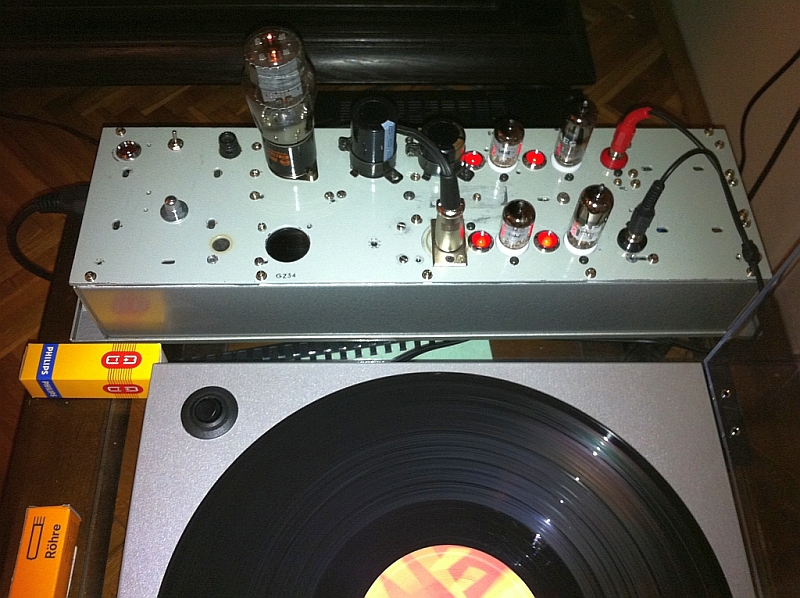
Here`s a photo of the finished and working preamp. I used an old chasis, and reused old holes...for the ugly large holes between the tubes I actually used 10 mm red LEDs. They look funny, and give a bit more voltage (and light) then their 5 mm brothers, about 1,82V with 11 mA.
And here`s an inside view , this is my version of compact unit and „old school" microelectronics. It looks like Frankensteins cell phone, actually...
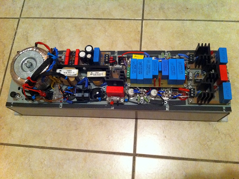
There are six PCBs inside, four of them are CCS modules, PCBs are my design, but someone can always use the kits. We have capacitors PCB (those ERO caps are radial), and heater regulator PCB, mounted on L sized heat sink.
I don`t have pro-measuring devices, and I used what I have (oscilloscope, multimeter, test CD). The results are good:
-with D3a/E180F combination, I measured A=292 times on 1 kHz, over 400 times with D3a/D3a...but sonically I prefered the former set a bit.
-the frequency response was tough to measure with my equipment, but if we can trust it, we have a nice flat response (0,1...0,2 dB deviation) through 50 - 500 Hz, with a gentle rise to the final 0,46 dB on 20 kHz.
-noise level is very low, with normal listening level you can hear it a bit with your ear close to the twitter.
-overload margin is very good too ( >33 dB or better on all frequencies, 20Hz-20 kHz)), you can put out over 100 Vpp from this preamp with ease, and this can be heard!
Subjective, after a few tens of hours of burn-in, tubes rolling, other little changes and experiments, I`m very pleased with the sound - open, dynamic, powerfull, clean, „fits" good with my SET, and now I`m listening LPs I didn`t listen to for decades. And I`m actually surprised with the excellent sound that many of these LPs have!
Be carefull about grounding and placing the components. I simply used local star grounds on each tube socket, and then one and only (star) ground on the chasis, close to the inputs. Total amplification on 50 Hz is about 2000x , and if we have only 10 uV of 50Hz mains hum induced somehow on the input, that means 20 mV on the output, or only 35 dB below nominal output.
This is a short version (haha) of this practical design. Unfortunately, I don`t have enough time for details...but with a bit of DIY experience those little pieces of RIAA puzzle can be solved by potential builder.
All in all, I wanted to share this project with old forum...enjoy!
-
 Attachment: RIAA calc.bmp
(Size: 428.80KB, Downloaded 38766 times)
-
 Attachment: RIAA pre.bmp
(Size: 738.39KB, Downloaded 42284 times)
-
 Attachment: CCS.bmp
(Size: 540.40KB, Downloaded 38953 times)
-
 Attachment: RIAA preamp.jpg
(Size: 379.68KB, Downloaded 38104 times)
-
 Attachment: IMG_0385.jpg
(Size: 425.55KB, Downloaded 37105 times)
|
|
|
|
|
|
|
|
|
|
|
|
|
|
|
|
| Re: RIAA preamp project [message #68585 is a reply to message #68583] |
Sun, 17 July 2011 07:32   |
 FL152
FL152
Messages: 29
Registered: April 2011
|
Chancellor |
|
|
Morgan Jones: "It is difficult to design a pre-amplifier of acceptable noise and overload capability using this network („all in one go" equalization), so this topology can usually be excluded." Because of this, he used „split EQ" technique, and 3-4 stages preamps.
IMO/IME, it`s not that hard to build a quality 2-stage preamp with passive EQ in between, if we respect some basic things. One of the basics is that we must include output resistance of the 1st stage, as well as input capacitance of both stages into consideration. Ideally, output resistance of the 1st stage „feeding" RIAA EQ must have a very small impedance, at least this impedance must be a small part of the series RIAA resistor. In this case, variations between tubes and change in S/rp during work have a minimal impact on the RIAA accuracy, and „sound" of our preamp. It`s a designer`s „duty" to find workable combinations of tubes/topologies and RIAA RC values...and to check that in practice. 
Similarly, input capacitance of the 2nd stage (Miller!) is a part of the parallel capacitor in RIAA network.
Unfortunately, usually we can`t expect those RC values to „fit" into standard values available, and series / parallel combinations of resistors and capacitors are often a necessity...plus measuring its real values with good instruments.
|
|
|
|
|
|
| Re: RIAA preamp project [message #76987 is a reply to message #67165] |
Fri, 07 June 2013 22:29  |
 |
 gofar99
Messages: 2015
Registered: May 2010
Location: Southern Arizona
|
Illuminati (5th Degree) |
|
|
Hi, I recently found a good way to test phono preamps. You need to build a reverse RIAA filter (not to difficult and only about 6 parts) and then the way I do it is use a DSO that has a built in signal generator and can do direct Bode plots of the results. With a good RIAA inverse filter the result should be a straight line. Mine is accordingly within +/- 0.2 db from 20HZ to just past 22KHZ. Ruler flat in the 100-10K range. The S/N is right on - 89dbv with common JJ ECC803S and ECC81S tubes. Low noise ones can bring it down about another 3 db. I stuck with the passive filtering as it seemed to sound better. Hard to define how, just better.
BTW you are quite correct that good grounding is extremely important. Layout is equally important. This is the type of project that can not be just thrown together and expected to work well.
Good Listening
Bruce
|
|
|
|
Goto Forum:
Current Time: Wed Feb 04 21:04:13 CST 2026
|


