| Kappalite 3015, DE250, QSC 152i waveguide [message #64302] |
Tue, 12 October 2010 12:14  |
 dprice
Messages: 10
Registered: November 2009
Location: Florida
|
Chancellor |
|
|
Wayne,
What attenuation level do you suggest to match the kappalite 3015 to the DE250? 8 db (12/20/0.47 for R1/R2/C1)?
Any other suggestions? I've some spare inductors and caps to experiment on the woofer low pass.
Last but not least, is the 4pi crossover board pricing each or per pair?
Thanks,
Don
|
|
|
|
|
|
|
|
|
|
|
|
| Crossover configuration [message #64331 is a reply to message #64330] |
Wed, 13 October 2010 22:14  |
 |
 Wayne Parham
Messages: 19000
Registered: January 2001
|
Illuminati (33rd Degree) |
|
|
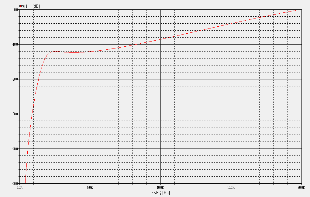
Any compression driver on a CD horn will be much louder below 4kHz, which is where mass-rolloff starts. Another thing I see pretty often, a common symptom of many conical horns and waveguides, is some quarter-wave peaking down low. This increases amplitude at lower frequencies and tends to further increase the difference of amplitude above and below mass rolloff.
That's what top-octave compensation is for, and you'll be able to manipulate the response curve by manipulating values of the π pad. The specific values for R1 and R2 and optionally C1 and/or Rs are different for each combination, so what works in my four π loudspeaker may or may not work for your application. But the topology most certainly will work, it's a strategy that is applicable to all constant directivity horns using compression drivers.
Your task will be to find the right component values to use. You may want to move the HF and/or LP crossover frequencies a little too, and you may need to play with the number of poles (2nd order, 3rd order) to get the position of the forward lobe where you want it to be. As I mentined earlier, this process is described in the "Crossover Optimation" thread.
The values of R1 and R2 are used to set attenuation below mass rolloff as well as to set the amount of damping for the high-pass filter circuit. This is generally set to provide a shelf response for the first couple of octaves before augmentation begins, countering mass-rolloff. Alternatively, if the horn's second impedance peak is in this area, it may be that more damping is needed to counter this. So optional component Rs can be used to provide additional driver damping, effectively swamping the driver impedance peaks.
These resistors form a π pad, with R1 being the series attenuator and R2 being the input shunt. The output shunt/load is the complex impedance of the compression driver, whose voice coil inductance provides increasing impedance and forms a natural 6dB/octave filter that conjugates mass-rolloff. So while R1 and R2 are the most important components of the π pad, components Rs and C1 are used to tailor the response further, where required.
Shunt resistor Rs can placed across the compression driver for impedance control. If all impedance peaks are below crossover, the Rs shunt is not used but if any are slightly above crossover, then Rs will probably be needed. It is generally sized at 2x voice coil resistance, Re. In your case, I think it is needed because it looks like there is an impedance peak around 2kHz, which is mirrored in the response curve.
Bypass capacitor C1 is often placed across the series attenuator resistor R1 to provide top-octave compensation. This may be needed in cases where driver inductance isn't high enough to fully conjugate mass-rolloff or where Rs is used, swamping it.
Sometimes, horns will need a little more electrical peaking, to prevent the top-octave compensation from forming a diagonal line. Sometimes they'll need more damping, to reduce a quarter-wave peak that is present. It all depends on the horn. But like I said, the beauty of the π crossover is it allows tailoring of the response curve, setting the amplitude below 4kHz independently of the response above 4kHz, while also providing the right 6dB/octave boost for top-octave compensation equalization.
 Desired transfer function for the tweeter circuit - the π Speakers crossover network
 |
|
|
|


