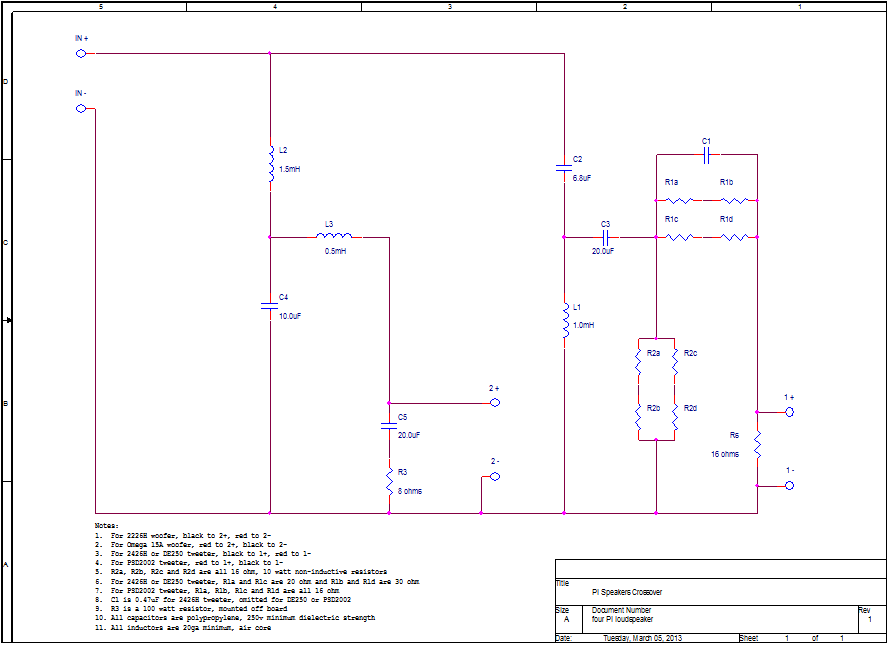
To use a 4Ω woofer, scale the caps and coils on the woofer circuit and also increase tweeter attenuation by changing the values of R1 and R2. This is because the 2226G (4Ω) woofer is 3dB louder than the 2226H (8Ω) woofer given the same drive voltage.If you're using a PSD2002-8, then R1 and R2 are normally 16Ω each. You'll want to increase R1 to 25Ω if the woofer is 4Ω. If you're using a DE250-8, then R1 is 25Ω and R2 is 16Ω. You'll want to change R1 to 30Ω and R2 to 14Ω if the woofer is 4Ω.
You'll notice the schematic below shows R1a, R1b, R1c and R1d. Likewise, there are components R2a, R2b, R2c and R2d. The circuit board layout has space for 10 watt non-inductive resistors like those from Mills or Dayton. The idea is to combine series/parallel components to form the desired resistance values of R1 and R2, while at the same time having a lot of thermal capacity.
For reference, a chart of woofer circuit values are shown below:
Component 2226G (4Ω) 2226H (8Ω) 2226J (16Ω)
===============================================================
L2 0.75mH 1.5mH 3.0mH
L3 0.25mH 0.5mH 1.0mH
C4 40uF 20uF 10uF
C5 40uF 20uF 10uF
R3 4Ω 8Ω 16Ω
===============================================================


