|
Home » Sponsored » Pi Speakers » Matching directivity in the vertical and the horizontal planes
| Matching directivity in the vertical and the horizontal planes [message #52293] |
Tue, 08 July 2008 17:52  |
 |
 Wayne Parham
Messages: 18996
Registered: January 2001
|
Illuminati (33rd Degree) |
|
|
One of the main reasons I have always used asymmetrical horns is to match directivity in the vertical plane as well as in the horizontal plane. I have always found the matched-directivity two-way configuration to sound very smooth because it generates a uniform reverberent field. But it isn't enough to match the horn's horizontal pattern to the pattern of the midwoofer at the frequency where it collapses; It is also important to match the horn's vertical pattern to the vertical null angle caused by driver position on the baffle.
When drivers are stacked vertically on a baffle, nulls form above and below the speaker. If these nulls are placed just outside the horn's pattern, they serve to punctuate pattern control in the crossover region.
When you crossover a direct radiator to a 90° CD horn, assuming they are in phase on the forward axis, summing is constructive on-axis as well as off-axis in the horizontal plane even at large angles. So the pattern narrows smoothly from being nearly omnidirectional at low frequencies down to approximately 90° at crossover, where it remains because of the horn.
In the vertical plane, nulls form above and below the speaker at an angle set by the distance between drivers and the frequency range of the overlap in the crossover region. This is usually somewhere between 40°-60°. At 20°-30° above the forward axis and at 20°-30° below the forward axis, nulls develop. These limit vertical coverage to 40°-60°, no matter what the horn's directivity is at that frequency.
If the 90° horn is axisymmetric, then the pattern widens back up again above the crossover frequency. So the directivity of the horn is not matched to the null angle in the vertical plane, and there is some ripple through that region as a result.
A horn with narrow vertical pattern is useful for matching directivity with the angle of the nulls in the vertical plane. If a horn is used that has 40°-50° vertical pattern, then the pattern does not widen above the crossover region. In the crossover region, the pattern is set by the off-axis nulls, and above the crossover region, it is set by the horn.
Sometimes, a horn is used that is not large enough to provide pattern control at the lowest frequencies. In this case, the pattern widens up briefly above the null frequency, and then settles back down as the horn gains pattern control. But even in that case, I think having an asymmetrical horn provides more uniform spectral balance overall.
My conclusion is a horn with 90°x40° or 90°x50° coverage is very useful for loudspeakers with vertically stacked drivers. The dimensions of the drivers (setting the spacing between them) and the crossover points needed all seem to come together using these angles.
|
|
|
|
| Re: I'm beginning to get that painful itch [message #52295 is a reply to message #52293] |
Wed, 09 July 2008 14:22   |
 Bill Epstein
Messages: 1088
Registered: May 2009
Location: Smoky Mts. USA
|
Illuminati (2nd Degree) |
|
|
|
Shingles always act up when I come across formulas. The subject of driver spacing in the link is interesting, tho', cause of the way some of us just perch horns on top of the box. I would imagine, with Pro 4Pi components, 2226 and DE-250, we can look at the Pi Pro4 box and get a sense of proper spacing? What about those of us that depart from the 2.5 cu ft box and use a 3 or 3.5 cu ft 3677 or a clone thereof like my BatSpeakers? (Hold on a minute while I measure my speakers...) ...It's 18" from center of woofer to center of comp driver with horn/driver on top. The baffle is 24x32. Does the new crossover have a different effect? What would be the optimum spacing for the 24x32 baffle? How different would the sound be going from 3.5 to 2.5 cu ft? When will they find UBL?
|
|
|
|
| Baffle spacing, null angles, etc... [message #52297 is a reply to message #52295] |
Wed, 09 July 2008 18:42   |
 |
 Wayne Parham
Messages: 18996
Registered: January 2001
|
Illuminati (33rd Degree) |
|
|
Whenever anyone asks about mounting horns on top, I usually remind them of the baffle spacing issue and how it relates to the null angles. It is best to keep the physical relationships between woofer and tweeter the same as designed, i.e. horn mouth flush with the baffle and distance between woofer and tweeter the same as shown in the plans. This ensures that everything will work properly and the nulls fall where they are supposed to.
This applies to cornerhorns as well as the DI-matched two-ways, because each has vertically stacked sound sources. The difference is one uses a direct radiating midwoofer, matching the horizontal coverage of the horn to the collapsing directivity of the midwoofer. The other uses a pair of horns with equal horizontal angles. In each case, the vertical angle is set both by horn radiation and null angle. It is desirable to have the null angle outside the horn's vertical pattern.
The π tweeter wood horn is a little taller than the H290, so it provides better vertical pattern control. The vertical beamwidth is less than 60° at 2kHz and gradually narrows to 40° by 8kHz. Polar charts are provided at the link.
The H290 is a little smaller, so it can't maintain vertical control much below about 4kHz. That means off-axis response outside the null angle will rise in the octave between 2kHz and 4kHz, and then fall back down as the horn gains pattern control. It is what I meant when I described a slightly undersized horn. It is a nice size though, and performance is good. Makes packaging convenient and attractive for the traditional DI-matched two-ways with the horn mounted in the box.
The tweeter in the four π has a slight horizontal offset, so the horizontal off-axis response curves are slightly different left than right. Not by much though. You can see in the charts below, the set of measurements on the left were done at angles that put the measurement microphone closer to the tweeter, resulting in a little less HF droop at large angles. But all in all, the curves are nice and smooth at all angles in both directions +/-50°.
Measurements gathered for various angles in the horizontal plane as well as the vertical plane. They were done with the speaker standing upright, but angled slightly downward so that the forward axis pointed at the microphone. The forward axis was defined as a line perpendicular to the baffle starting from the midpoint of the baffle, centered from top to bottom and side to side. The microphone was placed on the ground ten feet away.
You can see that the left chart doesn't falloff at HF as much as the chart on the right. That's because the left chart was done for vertical angles up from the forward axis, which puts the microphone closer to the tweeter. The 10 foot distance to the speaker's center was maintained, but the microphone moves up, so the tweeter becomes closer. Small angles, 10° and even 20° don't cause much HF drop, about 2dB each above 10kHz.
The right chart shows microphone movement downward, both increasing the vertical angle and the distance to the tweeter, so HF falloff is more pronounced.
Another thing that is interesting is the behavior at the null angles. Pay attention to the four curves: on-axis (black), 10° (blue), 20° (green) and 30° (olive). You can clearly see the valley produced by the off-axis nulls between 1.2kHz and 1.4kHz. Above the nulls, output increases to approximately 4kHz, where the horn gains pattern control and output falls back to about the same level as the valley formed by the nulls in the crossover region.
This is an indication that the H290 horn doesn't have good pattern control in the vertical plane until about 4kHz. It's just too small. A larger horn would have better vertical pattern control, so there would be less rise between 2kHz and 4kHz. But then again, the horn would have to be a lot taller to provide any real benefit, and that would increase driver spacing. The net result would bring the nulls closer together and adversely affect the shape and size of the forward lobe. All-in-all, it is probably not prudent to choose pattern control in the vertical over driver spacing.
A good balance is the best approach, which is why I tend to think this general size and form factor is the best compromise. Performance is of the H290 is very good and it is a nice size for the four π cabinet.
|
|
|
|
|
|
|
|
|
|
|
|
| Measurements [message #52418 is a reply to message #52293] |
Wed, 06 August 2008 13:49  |
 |
 Wayne Parham
Messages: 18996
Registered: January 2001
|
Illuminati (33rd Degree) |
|
|
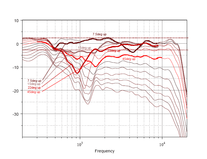
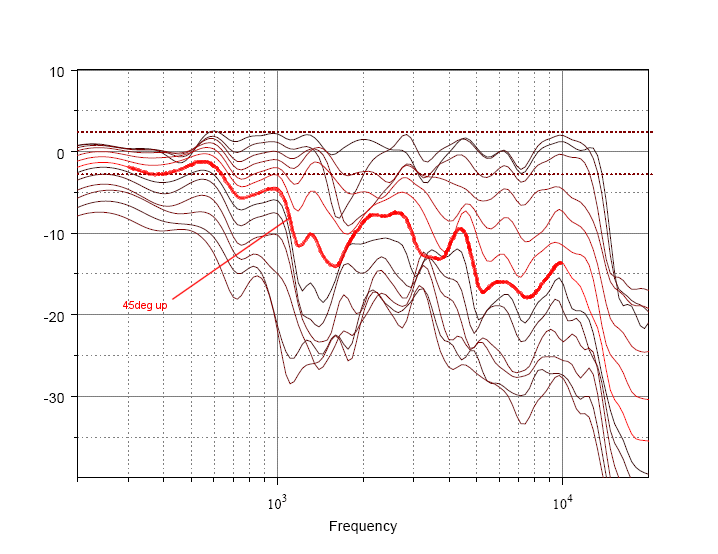
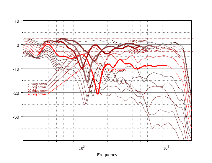
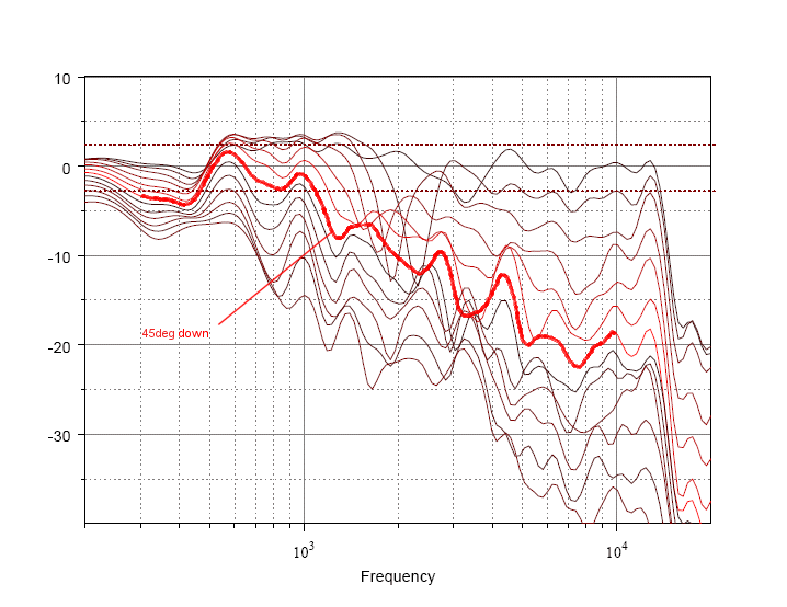
Below are vertical off-axis charts of two similar loudspeakers, one with an asymmetrical 90°x40° CD horn and another with an axisymmetrical round 90° CD horn. Both are matched in the horizontal plane so that horizontal directivity is approximately equal at the crossover point.
The speaker with the 90°x40° horn does not have particularly impressive on-axis response, so it may not be the best example. The measurements were done by the person selling the speaker with the round horn, so it is understandable that he would choose a speaker that is an easy target for a favorable comparison. But disregarding the ripples in response, you can still see a trend. The separation angle between vertical nulls and the lack of high-frequency output at large vertical angles is what I'm focused on. You can clearly see the difference, and these measurements demonstrate the off-axis response I chacterized with illustrations in the last post.

90° round horn up

90°x40° horn up

90° round horn down

90°x40° horn down
The trend is clear. At large vertical angles, both have a dip in response in the crossover region due to anti-phase nulls. Above the crossover frequency, the round horn response rises but the horn with narrow vertical coverage does not. The horn with smaller vertical pattern has less output at HF, and in this case at the edge of the +/-20° pattern it is roughly equal to the amplitude of the nulls. This is good coverage because we don't want or need HF at high vertical angles so the asymmetrical pattern is desirable.
As an example, pay attention to the 45° curve. At this angle, the speaker with the round horn is still in the pattern but the one with the asymmetrical horn is outside the pattern. So the speaker with the round horn has strong HF output at wide vertical angles but the asymmetrical horn does not.
Another thing that poses a problem is the vertical distance between sound sources. A round horn requires more vertical distance, making the null angle smaller. Here a trade-off is in order, because a larger mouth improves pattern control but it also requires more distance between sound sources stacked vertically on a baffle. It doesn't make sense to use a horn with good pattern control only to have nulls form within the pattern, so a useful tradeoff is to make the vertical dimension smaller to limit the vertical distance between sound sources.
If the null angles are spaced so they approximately equal the vertical pattern at HF, the nulls serve to marke the edge of the useful pattern. Beyond this, sound falls off. There is little treble outside the null angle. However, if a round horn is used with tall vertical coverage angle, then the nulls are in the middle of the pattern. There is still strong HF energy at large vertical angles but there is an anomaly in the crossover region. This is undesirable, as there is little need for sound at these large vertical angles.
|
|
|
|
Goto Forum:
Current Time: Sat Jan 24 16:01:28 CST 2026
|


