|
Home » Sponsored » Pi Speakers » 12 π basshorn - just about ready for prime time
| 12 π basshorn - just about ready for prime time [message #47284] |
Fri, 08 July 2005 00:51  |
 |
 Wayne Parham
Messages: 18991
Registered: January 2001
|
Illuminati (33rd Degree) |
|
|
Development of the 12 π is just about done. After working on the cooling system, I'm confident of the size needed for the system and so I worked on basshorn models that could implement the improved features. The requirements of the horn are that it have good response even when used alone, that it incorporate symmetrical drive and that it have improved cooling for increased power handling and reduced compression at sustained high power levels.
I'm very excited because I am confident this design provides all this and more. It all just came together in what I think is a wonderful new design.
For those who aren't already familiar with the development of the 12 π basshorn, I've written a brief history with some links to past discussions. Links are provided below for the history and some other observations. But for now, onto the technical discussion.
The 12 π basshorn is a 30Hz horn that provides reasonably flat response even when used alone. When used in pairs or singly but placed in a corner, response is even more impressive. A pair of drivers are used in push-pull configuration to reduce harmonic distortion. Between the reduced excursion of horn loading and the improved symmetry of the push-pull configuration, distortion is lower than standard horn loaded speakers or direct radiators with shorting rings. This system takes advantage of everything to make distortion as low as possible. And the use of a heat exchanger reduces heat build-up in the motor, so compression is reduced and power handling is increased.
In short, there's nothing like it.
That may seem a bit of an optimistic statement, and maybe it is. But the models make me bristle with excitement. Between the models and the initial cooling system measurements, I'm confident that this basshorn sets the standard. I'll have the prototype built in the next few weeks and we'll see.
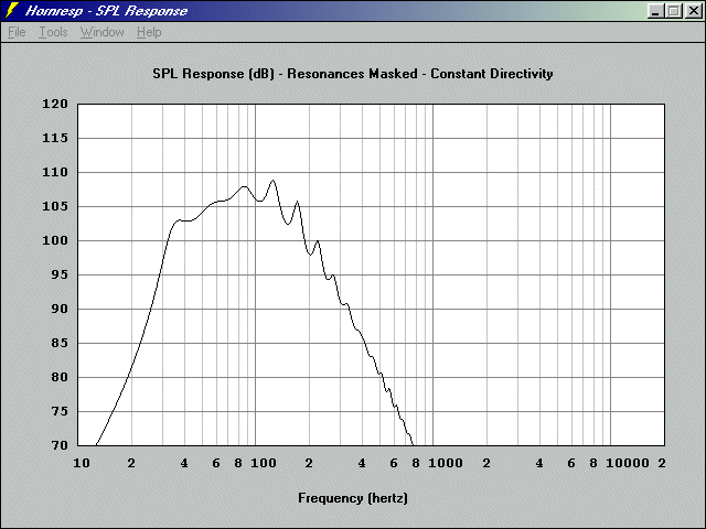 Single 12 π basshorn response, floorstanding in open space, 2.83VRMS input
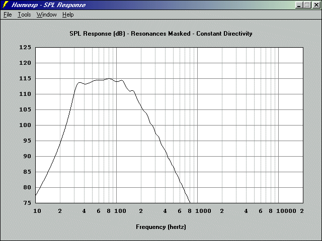 Response of four 12 π basshorns, or a single horn standing in a corner, 2.83VRMS input
Dimensions for this horn are just under 4' x 4' x 2.5'. At approximately 33ft3, it's not a small horn. But that's what it takes to get decent response from a horn. Other smaller horns require several clustered devices to get the same response as a single horn or small number of horns like this provides. So I think the 12π hornsub provides a lot of benefits without a lot of trade-offs. It's a no-compromise design.
Now let's look at performance on the juiced end.
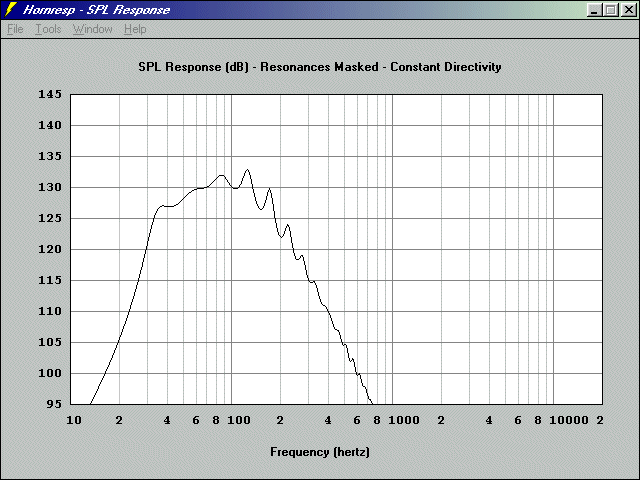 Single 12 π basshorn response, floorstanding in open space, 45VRMS input
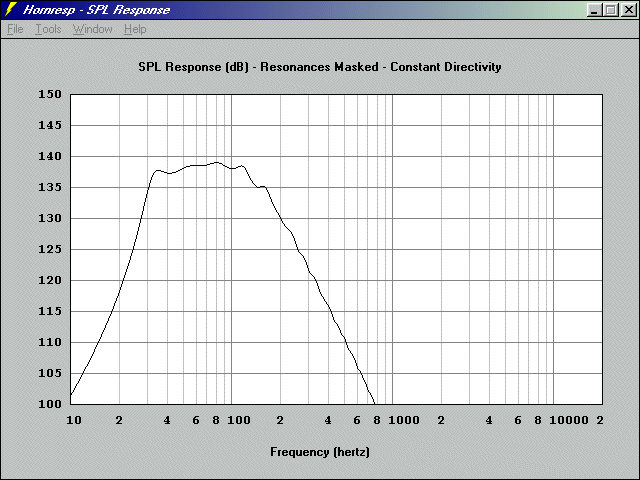 Response of four 12 π basshorns, or a single horn standing in a corner, 45VRMS input
According to Hornresp, the speaker is quite capable of good response and very high output.
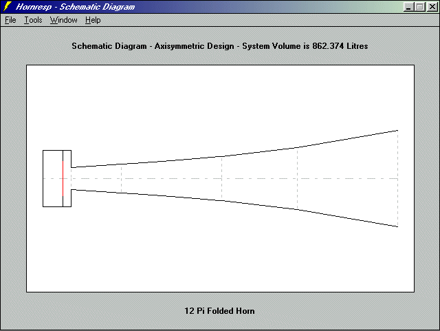 12 π basshorn, simplified flare profile
The driver chosen is the LAB12, and its mechanical limits are reached at 44mm. At 28Hz, excursion peaks, but it is common practice to high-pass a subwoofer like this if it is pushed hard. If source material is limited below 30Hz, then the device can be expected to never reach its mechanical limits. And since a heat exchanger is used to remove heat from the motor chamber, thermal limits are greatly increased too.
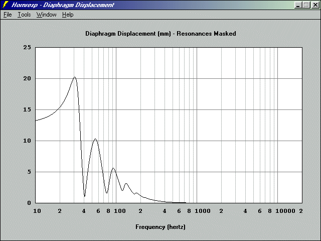 Driver excursion of 12 π basshorn at 45VRMS input
The shape of the horn is pretty basic. It is very much like some of the other common basshorn designs, but a little larger than most of them. I considered several folding arrangements. The scoop-style of the earlier ten π, the W and Z style fold and the spiral all were examined. One thing that complicated my decision was the fact that the cooling system might have needed extra space, and it might have needed the drivers to be placed near an external cabinet wall. The W shape allowed both drivers to be placed near the back wall, so I had that in mind. But the spiral had been adopted by so many folded horn builders, that it allowed me to develop a cooling system compatible with all horns. So I chose it as well, thus making the heat exchanger designed for the 12 π to be compatible with the LABhorn and ServoDrive horns, BassMaxx and Fitzmaurice basshorns, as well as many others.
 12 π basshorn, side view
The folding geometry is not unlike other designs, with the biggest difference being the front chamber and the throat. Another important difference is the push-pull arrangement of the drivers:
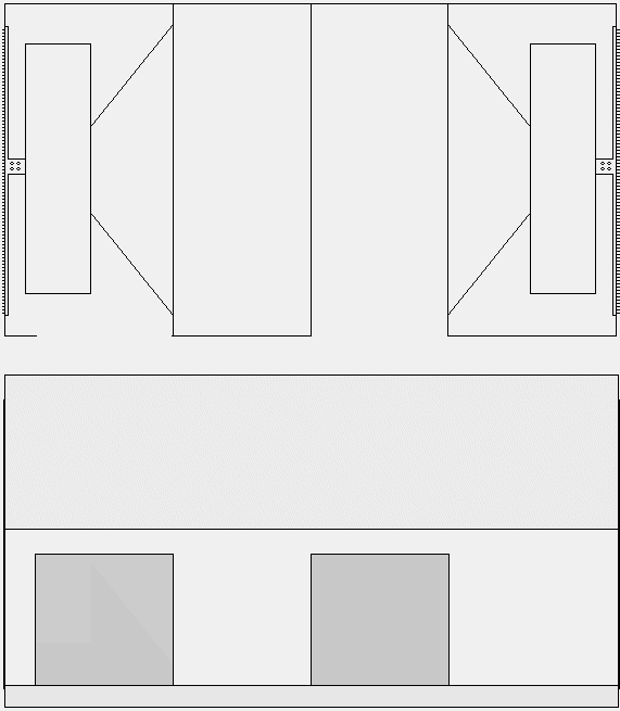 12 π basshorn motor chamber detail
Another important difference is in the cooling system, which doubles as an access plate. By removing the heat from the inside of the box, the long-term thermal limits will be improved and compression reduced.
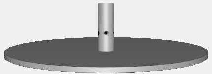 12 π basshorn Heat Exchanger and Driver Access Panel
A quick word about the cooling system. I explored a lot of possibilities, and one in particular was very interesting and potentially beneficial. The one I chose was a simple heat exchanger with a metal rod that connects the hot center pole piece to a large aluminum panel. We found it to be simple and effective. But we also made an air pump that worked quite well and it could be used with an intercooler to remove heat. It also serves to muffle vent chuffing, which is of benefit for builders of dipoles, isobaric and push-pull direct radiators. But for this application, the front chamber will muffle the vent noise, so I don't think the added complexity of the ducting was merited. As I said, having the compatibility with other basshorns is attractive, since it lets us all use the same hardware for cooling.
I'm planning to build the prototype this month, and I'm anxious to verify its performance. But I trust the models. McBean's Hornresp was used to model the 12 π basshorn, and I've used it to model other horns in the past. The results have always had good correlation with measured response, so I am pretty comfortable with the models.
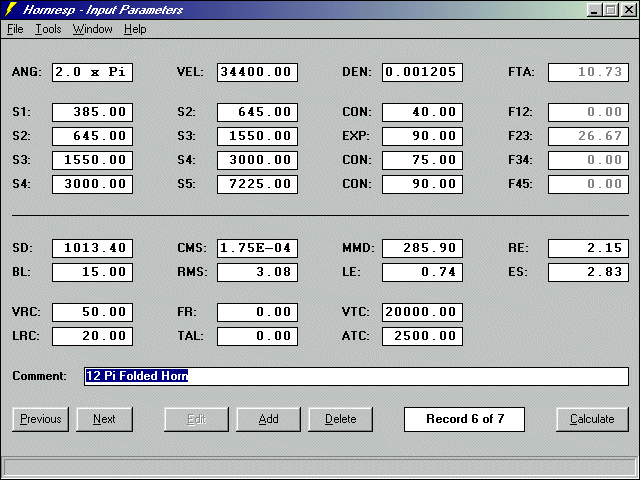 12 π basshorn Hornresp model input parameters
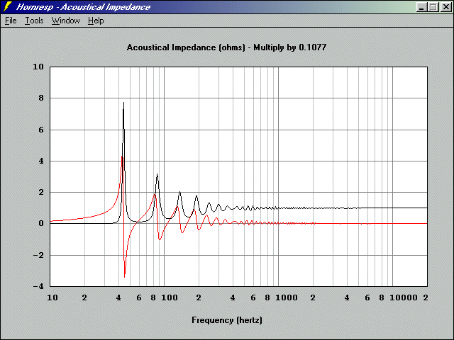 12 π basshorn acoustic impedance (single, freestanding)
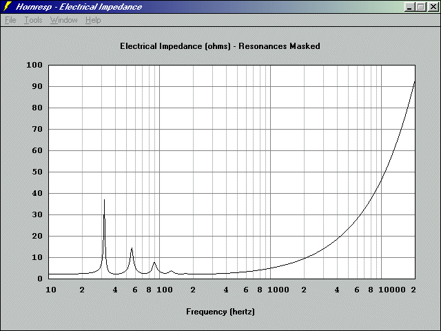 12 π basshorn electrical impedance (single, freestanding)
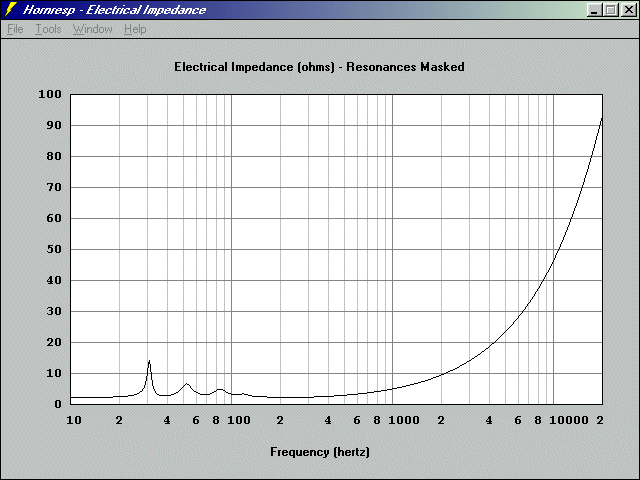 12 π basshorn electrical impedance (per horn) when four are used freestanding or one is used in a corner
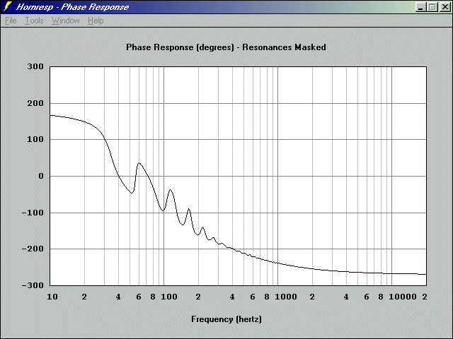 12 π basshorn phase (single, freestanding)
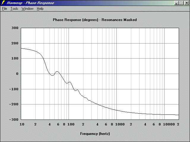 Phase of four 12 π basshorns
|
|
|
|
| 12 π basshorn development history [message #47285 is a reply to message #47284] |
Fri, 08 July 2005 02:03   |
 |
 Wayne Parham
Messages: 18991
Registered: January 2001
|
Illuminati (33rd Degree) |
|
|
There are a lot of little details about the 12 π that I think are important enough to mention, but they aren't directly related to the current implementation of the device. So I thought I would write about them separately.
The 12 π was made largely in response to the LABhorn, which is why there is such similarity. It's like an upgrade, an improvement to the LABhorn, much like Brad Litz's version. Like Brad's basshorn, there is much more output between 30-60Hz from the 12 π basshorn than the LABhorn, and that requires a little bit additional excursion. You can't get the bass for nothing. But there are a lot of similarities in each of these designs, and I think the size constraints along with the 30Hz requirement of the original LABhorn are what made it destined to have the tradeoffs that it has.
A few years back, just after the LABhorn prototype was built and tested, I commented about the response dip in 30-60Hz range and also about the choice to use woofers without shorting rings. My (1970's) ten π basshorns were designed for the 40-400Hz range, and they really benefit from woofers with shorting rings. The horn reduces distortion but the shorting rings reduce it even more. So I felt pretty strongly that the system would have been better if it had some mechanism to improve motor symmetry and if it didn't have that 30-60Hz dip.
In all fairness, the size dictates the response. Basshorns are sometimes made too small and if that's the case I'd rather have a direct radiator or a bandpass box. I don't like the peaky response of a basshorn that's too small. But if you group them together, that helps.
About distortion, I asked Eminence to make a woofer that contained a shorting ring. I could use it in my own horn, and it could also be used to retrofit LABhorns and used in other designs as well. It would also make a pretty fine small home subwoofer as a direct radiator in a vented box about 2-4ft3. So I had hoped to have a suitable woofer made with a shorting ring. What Eminence found was that they couldn't easily reduce distortion below 100Hz. That makes reduced effectiveness of the shorting rings for a basshorn that is intended to be used below 100Hz. It isn't that it can't be done - it can - but there are limits, and to push those limits lower in frequency requires the use of more metal in the motor, both in the conductive ring and in the magnet and return circuit metal required to make up the difference.
So I decided to make a basshorn with push-pull woofers instead. This helps motor symmetry by using two of the same woofers and connecting them in opposite directions. The things that cause asymmetry are countered pneumatically that way. When one motor is pushing in its weak mode, the other is pulling in its strong mode. Then they flip sides for the other half-cycle, both having a strong side and a weak side. This does the same thing as a shorting ring, but in a different way. It is more effective down at low frequencies because it is done pneumatically instead of electro-magnetically.
The problem now is that a push-pull basshorn throat has the magnet and vent of one driver and the cone face of the other. There were concerns about vent noise and cooling. I immediately started looking at ducting the cooling vent, which would muffle vent noise and also I could make improvements to the cooling system as well.
About a year ago, there had been time enough to start seeing LAB12 failures in the field and some were thinking maybe they were heat related. So the cooling system improvements looked like an excellent side benefit to pursue of this push-pull basshorn and its cooling system.
I must admit that I hadn't really inspected the LABhorn until the last couple of weeks. All of my previous comments were based on models and measured datasets. I had heard that some were using aluminum access panels, hoping for some heat conduction but it was only recently that I saw the plans for the LABhorn to know specific dimensions, and to see that the aluminum plate was there in the plans, not as an add on.
But I also had already done some measurements of the woofer, its vent and the heat generated and knew immediately that the access panel on the LABhorn wasn't doing any good as a heat exchanger. There's no thermal conduction path between the motor and the plate.
Air in the cabinet doesn't transfer much heat to the panel. Even the cooling vent air doesn't carry much heat - Most of it is radiated into the center pole and magnet. The air inside the cabinet is heated slowly by the magnet. And the air in the cabinet heats the access panel even more slowly. So the inside of the cabinet can get really hot, and then the one thing that marginally helps cool the voice coil - the air surrounding it - is too hot to do any good.
Since my thermal measurements showed that most heat is radiated into the pole piece, I decided to explore the use of a simple heat sink and heat exchanger instead of a ducted intercooler system. The front chamber of the 12 π horn and the folds will attenuate vent noise. Part of what made me decide to use the simpler cooling system is that its easier to implement and should be just as effective. The tube connecting the speaker center pole to the access panel will conduct heat very effectively. The second reason I shifted is that it is a solution that others can implement easily as well.
LABhorns in the field can be easily retrofitted to include this part. Just drill a hole in the existing access panels, and countersink so that the mounting screw is flush. Put the aluminum rod on the access panel and insert it into the magnet vent hole. The rod is hollow so air passes through it and out the cross-drilled port holes up near the access panel.
So the cooling system is just too simple to pass up. It can be used on lots of other basshorns in addition to the 12 π. All you really need to make it work is an aluminum rod with a few holes in it and an aluminum plate. Simple stuff that any machine shop can make at low cost. It's a lot cheaper than woofers. I'm anxious to get more data on how effective they are, because my initial tests are extremely promising.
That brings me up to the current day. I have the cooling system, the horn models and a lot of paperwork. Now it's time to build a prototype. Should have one within a month and I'm extremely optimistic.
|
|
|
|
| 12 π observations and comparisons with other designs [message #47286 is a reply to message #47284] |
Fri, 08 July 2005 02:53   |
 |
 Wayne Parham
Messages: 18991
Registered: January 2001
|
Illuminati (33rd Degree) |
|
|
The 12 π basshorn subwoofer was made largely in response to the LABhorn, and seeks to improve upon it. It's a basshorn I can get excited about. The 12 π is big enough to work well standing alone, and exceptional when used in pairs or groups. But it's still small enough to pass through 30" doors. With castor wheels, a 12 π basshorn sub can be wheeled across hard surfaces by one man. Lifting and carrying isn't going to be a joy, but it isn't going to take a forklift either.
I modeled a LABhorn for comparison. Here are the Hornresp models and simulation outputs:
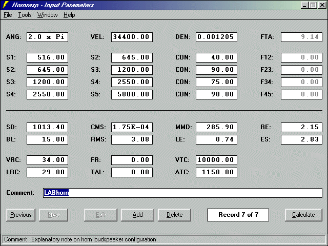 Hornresp data input for the LABhorn
 Hornresp data input for the 12 π basshorn
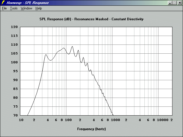 Single LABhorn response, floorstanding in open space, 2.83VRMS input
 Single 12 π basshorn response, floorstanding in open space, 2.83VRMS input
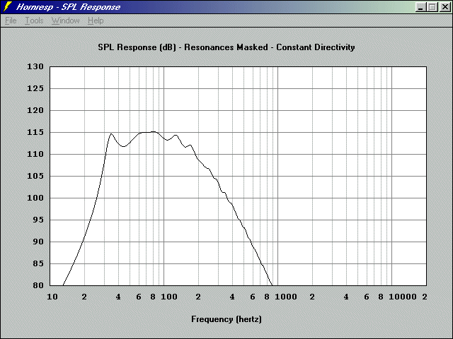 Response of four LABhorns, or a single horn standing in a corner, 2.83VRMS input
 Response of four 12 π basshorns, or a single horn standing in a corner, 2.83VRMS input
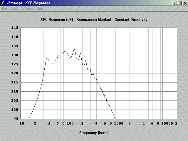 Single LABhorn response, floorstanding in open space, 45VRMS input
 Single 12 π basshorn response, floorstanding in open space, 45VRMS input
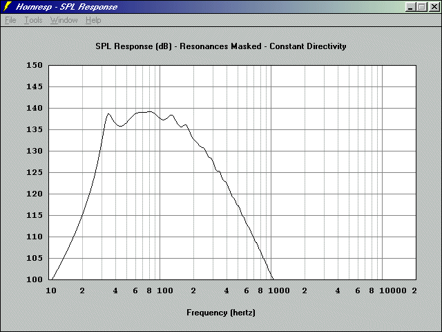 Response of four LABhorns, or a single horn standing in a corner, 45VRMS input
 Response of four 12 π basshorns, or a single horn standing in a corner, 45VRMS input
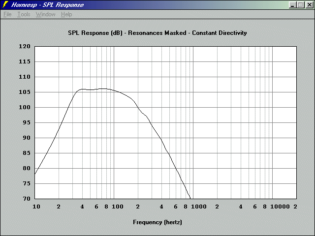 Response of a large group of LABhorns approaches this (infinite horn)
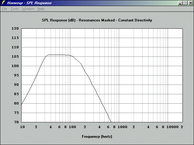 Response of a large group of 12 π basshorns approaches this (infinite horn)
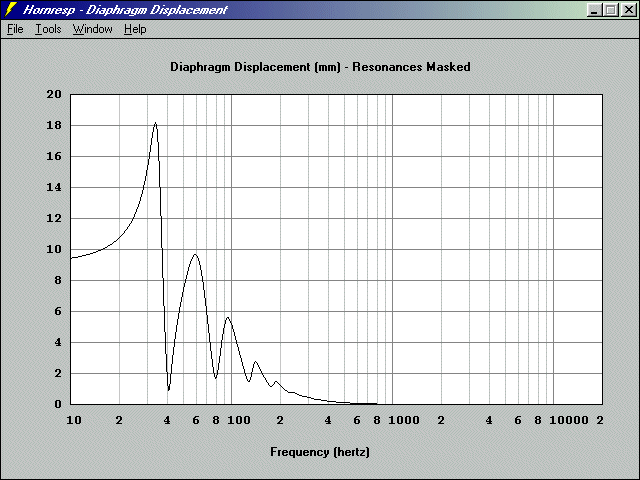 Driver excursion of LABhorn at 45VRMS input
 Driver excursion of 12 π basshorn at 45VRMS input
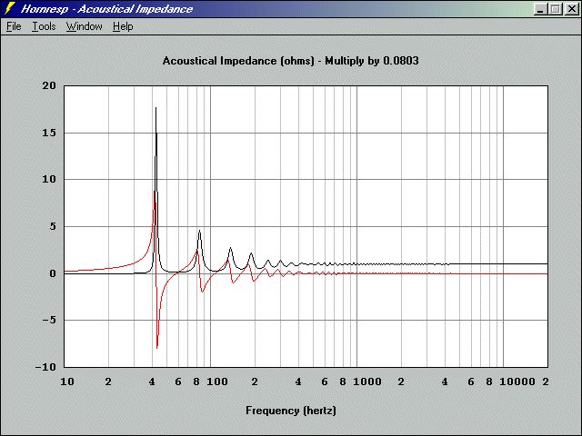 LABhorn acoustic impedance
 12 π basshorn acoustic impedance
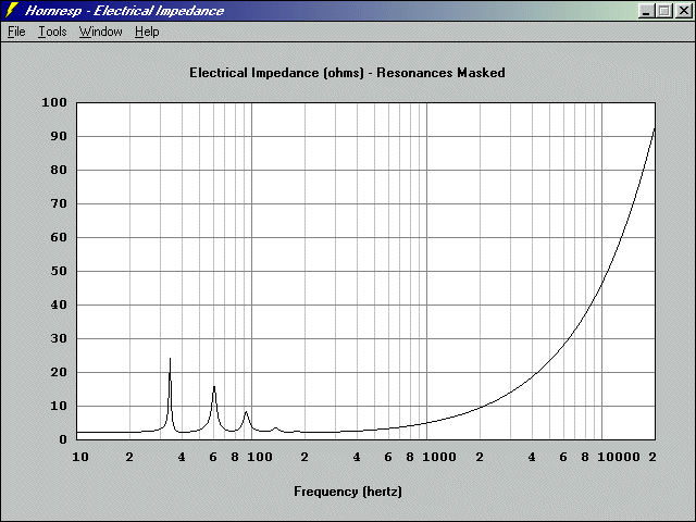 LABhorn electrical impedance
 12 π basshorn electrical impedance
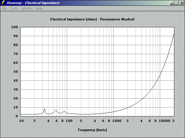 LABhorn electrical impedance (per horn) when four are used freestanding or one is used in a corner
 12 π basshorn electrical impedance (per horn) when four are used freestanding or one is used in a corner
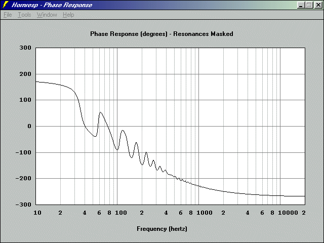 LABhorn phase
 12 π basshorn phase
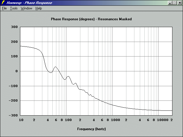 Phase of four LABhorns
 Phase of four 12 π basshorns
|
|
|
|
| Re: 12 π basshorn - just about ready for prime time [message #47287 is a reply to message #47284] |
Fri, 08 July 2005 06:59   |
 Walt
Walt
Messages: 16
Registered: May 2009
|
Chancellor |
|
|
|
Perhaps I am missing something but why don't you make the front chamber smaller: 20 litres instead of 50 litres. That will give a much flatter response which is more easy to use with standard subwoofer amps with build in bassboost. Perhaps you can open up the throat to 450cm2. I know the large 50 litre frontchamber will give a higher SPL max around 30Hz but for home use I would think the 20 litres frontchamber version sound better. Response in a corner will be +/- 2dB from 30-100Hz... Best regards, Walt
|
|
|
|
|
|
|
|
|
|
|
|
| Re: 12 π basshorn - just about ready for prime time [message #47292 is a reply to message #47288] |
Fri, 08 July 2005 14:05   |
 |
 Wayne Parham
Messages: 18991
Registered: January 2001
|
Illuminati (33rd Degree) |
|
|
As soon as we have the prototype 12 π hornsub ready, I'll measure it and report back.The idea of push-pull woofers is to reduce harmonic distortion by improving pneumatic symmetry. When a speaker is pushed hard, its drive force is increasingly non-linear. The causes are mostly due to heat and magnetic flux modulation. The force that moves the cone is not perfectly linear, and its back and forth motion is not perfectly symmetrical. This is because the magnetic field generated by the voice coil deforms the magnetic field of the fixed magnet. This causes eddy currents in the magnetic circuit, literally modulating the flux. Further, the magnetic circuit is made of several parts, the center pole, top plate and back plate, in addition to the magnet itself. These may saturate at different levels, which will also cause force asymmetry. The push-pull configuration corrects for this using two drivers connected as a complementary conjugate pair.
|
|
|
|
|
|
Goto Forum:
Current Time: Wed Jan 21 16:44:11 CST 2026
|


