You can biamp and use compensation components on the output, but if you put compensation on the input, you can generally use 10x less power. That gives you a lot more choices for suitable amplifiers.The π passive crossover is a complete system, and the R1/R2/C1 components shouldn't really be viewed as a stand-alone network. The response curve of these three parts by themselves is a diagonal line instead of the stepped response formed by the π crossover. But when used in the circuit having series (high-pass crossover) capacitance and (voice-coil) inductance, some peaking is introduced which raises the bottom portion of the response curve and makes a shelved region of flat response.
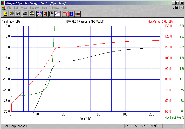
The resonance caused by crossover capacitance and voice coil inductance can be seen similarly to the resonance caused by a loudspeaker port. Using a specific Zobel or damping resistor, one can set the Q of the circuit so that response is flat, just like they would set the characteristics of a ported cabinet to make woofer response flat. But one can also choose to make the system underdamped or overdamped, or to create a shelved response like an EBS. As an example of this shelved response, see the response curve of an EBS woofer system:
 EBS woofer response from a vented cabinet using specific peaking
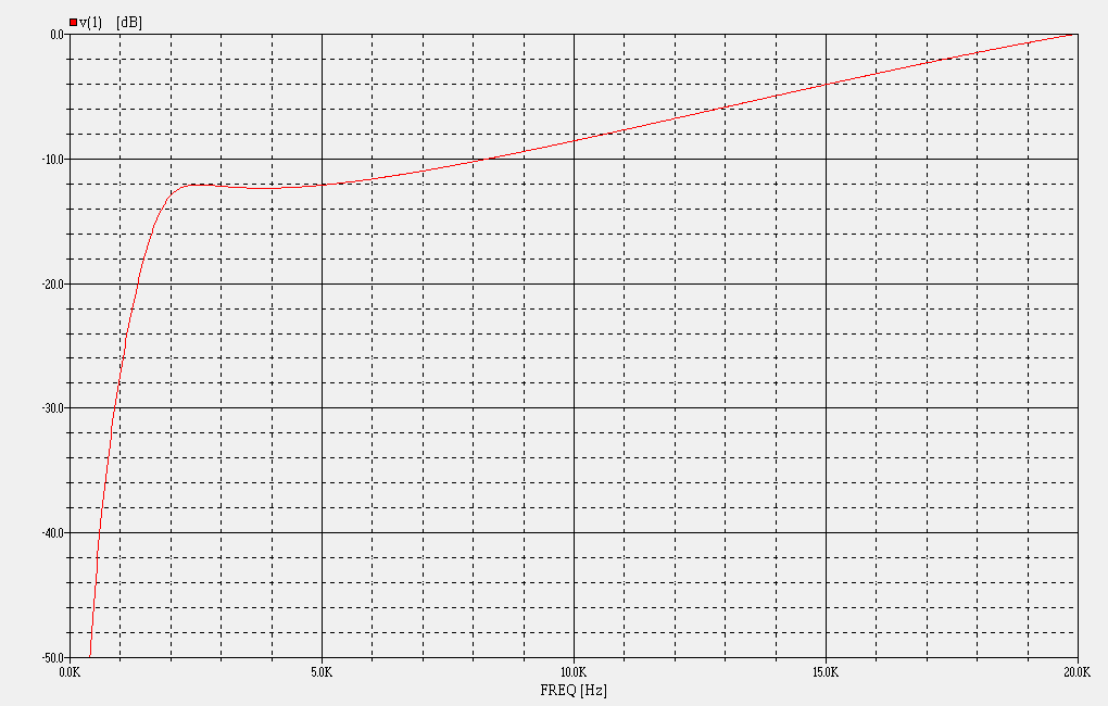
The π crossover essentially employs an EBS alignment with electrical components. It is specifically designed to be used with compression horns that are flat for a couple of octaves before they begin to rolloff. The π crossover is flat for a few octaves and then begins to rise, having response that complements the tweeter.
 Compression horn drive signal response from π crossover
So that brings us back to your situation. If we were to use just R1, R2 and C1, we may not get the response curve we need because the system depends on voice-coil inductance and series crossover capacitance. You'll still have voice-coil inductance, but you might not have the right amount of series capacitance in the output circuit.
That leaves you with a few choices:
1. Active crossovers sometimes have similar equalization built-in, in which case you can simply omit the π compensation components and switch the active crossover EQ on.
2. You can build a filter circuit for the input of your amplifier. This is a preamp-level compensation circuit that provides response like the π crossover. Or you can build your own active crossover that includes suitable EQ.
3. Compensation components R1, R2 and C1 can be installed in the output circuit, including the right amount of series capacitance ahead of the compensation components. The series capacitance will also serve as a protection component, and will form an additional first-order filter, so that should be included in your design analysis.


