Making a resistive voltage divider to form an L-Pad isn't very difficult, and I expect you'll find lots of websites that will tell you how to do it. It's simple Ohm's law, and you are trying to solve for two things simultaneously:1. Total series resistance equal to the desired load, i.e. 8 ohms.
2. Ratio between the two resistances to provide a proportional voltage drop corresponding to the decibel level of attenuation required.
This is all fine and good, and it does provide a specific load to the crossover network. But it doesn't necessarily set filter Q where you want it, which is usually overdamped with this kind of arrangement. It's usually better to set the shunt resistance - the load - a little higher than you might expect. The best way to find out is to analyze the circuit using a series of frequency points. And these days, it's very easy to do with Spice.
Since you say you're doing top octave compensation, I strongly suggest that you look at the Spice models contained in the archive above. Just click the link in the preceding paragraph and download the file.
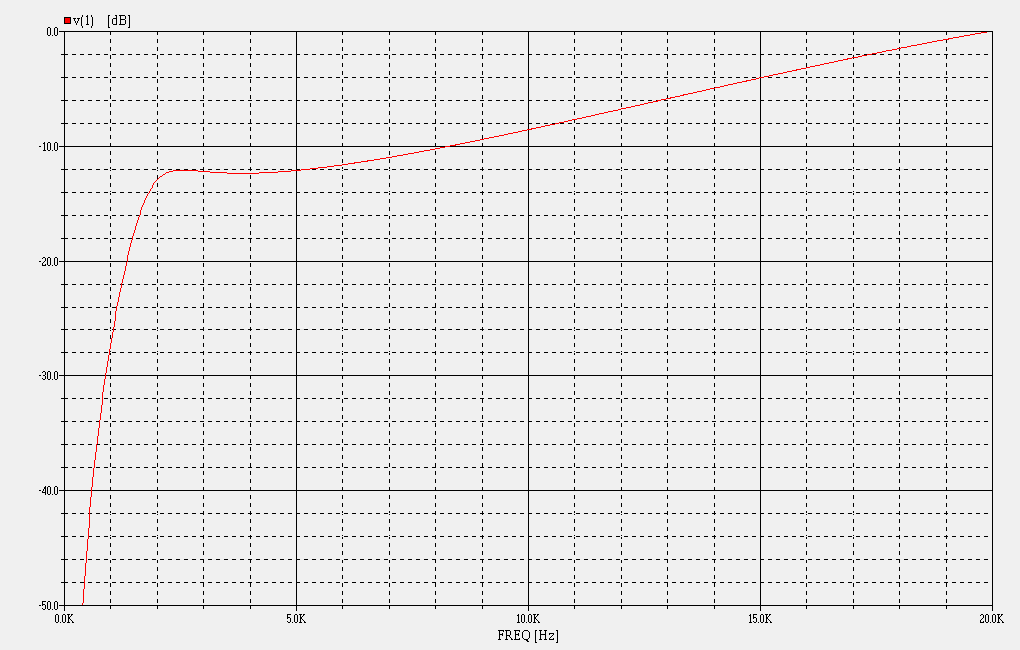
 Response curve for HF circuit of π Crossover
I've sent you mail that has a schematic for the π Crossovers, including 500Hz, 600Hz, 800Hz, 1kHz, 1.2kHz and 1.6kHz models. For each, you'll find a chart of values that will tell you a great circuit topolgy for your needs. You can set it for any amount of attenuation you like, and it will give you a nice response curve for compression horns needing top octave compensation.


