Check out the π crossover document for a complete description of various two-way networks and filter techniques. I'm sure there are other good ones out there too, but I wrote this one specifically to be reasonably readable, to illustrate issues with graphs, and to show the schematics of the circuits involved. It shows first, second and third order networks, and pays particular attention to phase. As you know, phase is another way of saying "delay."The moral of the story: Phase changes in a crossover as a function of frequency. Since phase moves, so does the amount of delay between subsystems. While the idealized first order low pass has a fixed rate, this is a specialized condition that is not found in the tweeter circuit. And it also requires the load be resistive, and that is not the case with speakers with voice coils. Even damped, the speaker is not anywhere close.
But let's look at it anyway, just to make things clear.
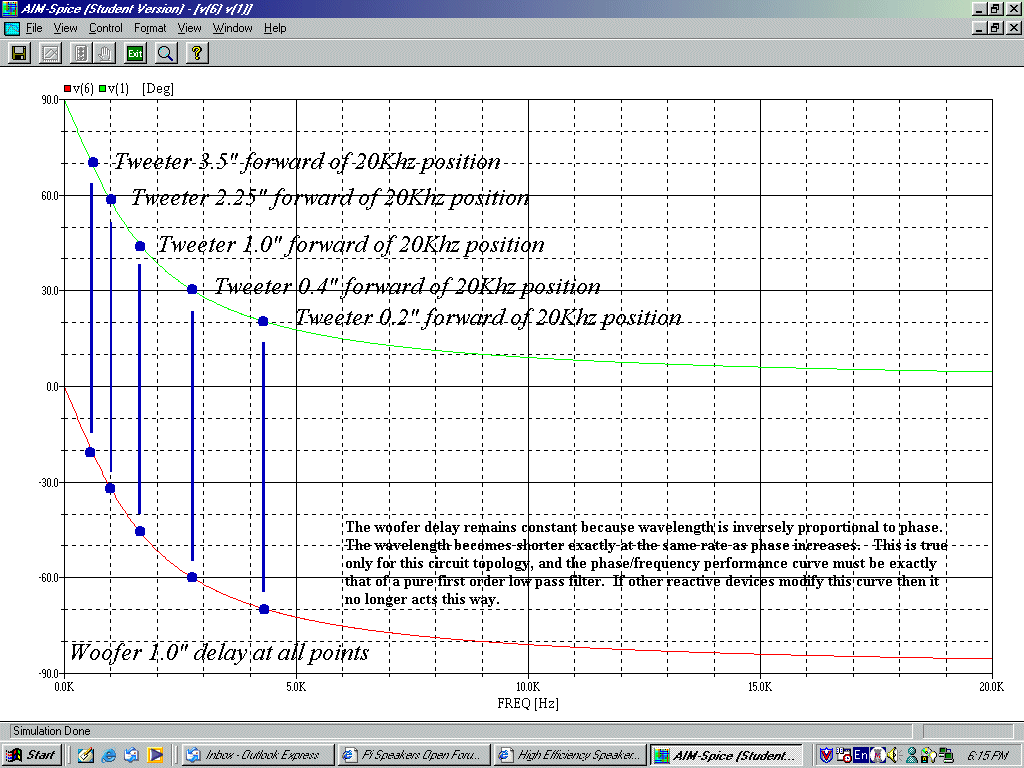
 Phase response of idealized first order network
The graph shown above is the phase response of an idealized first order crossover for a two-way system having a crossover at 1600Hz. This means that the components chosen have pure capacitance for the tweeter circuit and pure inductance for the woofer circuit. It also means that the speaker motors are perfect resistor loads. In this idealized model scenareo, we find that the woofer is shifted 1" further away from us through the points of interest.
But the problem is that the tweeter just won't behave. As we draw nearer to the asymptote, the apparent sound source position shifts. As we go further into the passband, the tweeter's apparent position moves. So you can delay the perfectly resistive woofer by a perfectly fixed amount. But you can't do this for the tweeter. As phase moves, so does the offset.
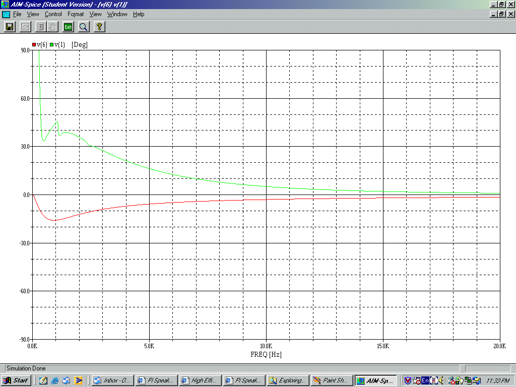
Now let's look at the real world. Here's what the phase looks like when a voice-coil woofer and compression horn tweeter are used:
 Phase response of actual first order network
Ouch! That one's "all over the map."
The components used in this case are the Eminence Delta 15 and the PSD2002 tweeter on the H290 horn flare. And really, those are more "well behaved" than many because voice coil inductance is unusually low. So all in all, this is typical of what should be expected of two-way speakers having a compression horn and a woofer.
The reactance of the tweeter makes a peaky phase curve, and the voice coil inductance of the woofer tends to make the crossover coil act more like a wide-band voltage divider than a frequency splitter. Some don't expect this interaction, and so their crossover filters don't work as they intend and response suffers. But you can also use this behavior to your advantage, as long as you know that it's there. The point is that interaction between driver and crossover reactances alters the frequency and the phase characteristics of an "idealized" network.
No passive network - high order or low order - can make a speaker "time aligned" with any baffle offset. This is true of a specific point in space on axis, where all driver diaphragms are fixed in their distance relationship to the listener. So you can imagine what happens when you move in 3D space off axis, where path length changes and one driver is made further from the listener than the other. As movement is made relative to one driver or the other and the listener, we move these offsets around even more.
That's why I sometimes bristle when I hear discussions of baffle offsets or fixed delays to create "time alignment." I much prefer to talk about constructive summing, because that is something we can work with.
Now then, what good is this information, you might ask. Does this mean there is no hope, no way to provide good sound anywhere except at a single pinpoint "sweet spot" location?
When you calculate out all the phase angles, driver positions and arrival delays what you find is that summing becomes destructive at set angles. If you position the drivers so that they sum constructively at the crossoer frequency on the forward axis, then the phase of the crossover and the delay from driver positions make the sound arrive in-phase on the forward axis. This will be the case at frequencies very near the crossover frequency. Naturally, the point of phase-zero constructive summing will shift as a function of frequency, moving the forward axis up as freqency rises.
The other thing that happens is there are two angles where nulls appear, one above the forward axis and the other below. The angles are determined by the distance between sound sources and the frequency sound that they are both generating. The reasons these appear is vertical movement causes a path length difference between the listener and the two sound sources. At certain angles, the path length distances are multiples of 1/2 wavelength, causing cancellation. So what you see is a forward lobe of in-phase summing surrounded by anti-phase nulls. Further out, side lobes appear if the sound sources angular coverage is wide. Unless the sound sources are horns with pretty tight pattern control, there is usually enough off-axis energy for the side lobes to appear out beyond the nulls.
OK, so now we know there are forward lobes, nulls and side lobes out beyond that. Now what?
Remember, you cannot hope to make a multi-driver loudspeaker generate a point-source spherical wave in all directions with uniform coverage. A single driver speaker won't do it because it has collapsing directivity, so high frequencies are much more directional than low. A coaxial driver won't do it because even though it is sort of like a point source, it has collapsing directivity like the single driver does, but when the woofer starts to beam, crossover is made to the tweeter wheich then widens back up again. So coverage is weird, going from wide to narrow to wide again, probably beaming yet again higher up. And a speaker with vertically stacked drivers has anti-phase nulls that form above and below, with an in-phase forward axis that drifts upward slightly through the overlap band.
But here's one way to work with all these factors to provide uniform coverage. While we want a wide horizontal pattern, vertical coverage doesn't need to be nearly so tall. The target area is usually much wider than it is high. There is no need to waste energy on the floor and ceiling, so a wide but short pattern is ideal. I like 90x40 because it can set in a room corner and cover the entire room. It is a useful pattern. It also happens that if you crossover around 1.2kHz to 1.6kHz with midwoofer (or dedicated midrange, for that matter) and tweeter center-to-center spacing of about 12", the vertical nulls are about 50o apart. That's a convenient angle when using horns with 40o vertical pattern.
Another thing happens around the same frequency that is useful in for the three π and four π loudspeakers. A direct radiator begins to become directional as frequency rises. The pattern is nearly omnidirectional at low frequencies, but by the time wavelength equals diameter, the pattern has narrowed to a cone shape of roughly 90o. So 1.2kHz to 1.6kHz crossover between a 12" or 15" midwoofer to a 90x40 horn just above it on the same baffle results in a pattern that narrows in the horizontal to 90o, and then hands off to the tweeter horn with matching directivity. The vertical angle is "squeezed" by the nulls down to 50o, and then as the tweeter takes over, it eventually narrows to 40o through the rest of the band. This is a great way to provide uniform directivity through a useful coverage angle.
There is one more thing to consider, and that's crossover slope. Low-order crossovers have a very wide overlap, so they aren't attractive for this solution. The wider the overlap, the greater the shift of the in-phase forward axis and the anti-phase null angles. As frequency rises, the forward axis drops and the null angles get closer together. So it is important to limit the overlap band. Of course, high-order slopes add more phase shift, so there are some limits to what you can do. High-order crossovers tend to also introduce more insertion loss, so second and third order filters are probably the best compromise between reducing the width of the overlap band without causing too much insertion loss.


