| Guinevere construction [message #30455] |
Fri, 11 February 2005 12:28  |
 PakProtector
Messages: 935
Registered: May 2009
|
Illuminati (2nd Degree) |
|
|
Hey-Hey!!!,
I don't remember if Damir's proposed layout for the plate loads/CCS design has the MOSFET's set at right angles, but I suggest that you do it that way. It might also be best to put them at opposite corners of the board too. they seem to be able to interfere with each other ( at least the littler TO-92 can be put close enough to get in each other's way I think ).
regards,
Douglas
|
|
|
|
| Re: Guinevere construction [message #30459 is a reply to message #30455] |
Fri, 11 February 2005 13:36   |
 Damir
Damir
Messages: 1005
Registered: May 2009
|
Illuminati (2nd Degree) |
|
|
I sometimes hate this hobby... Marphy`s Law constantly works against you, every little "trick" you learn hard way, and sometimes I`m not that patient... In the last three days I worked on the small PCBs for the CCS... I somehow ruined three prototipes so far, break nice 0,8mm bore, etc - but the fourth looks promissing. I`d (probably) post a picture in a day or two. In my prototipe I put one transistor on the upright heatsink, and other from the other side of the sink ("shield"), 90° angle between them. I was tempted to put about 50 various "stoppers" in the first version, but finally I`m building it simply, we`ll see. Unfortunately, it`s the MJE350/BC558B/LED CCS and not 2 x DN2540, but the principle can be seen. When I think about it - all that capacitances between the PCB traces just call for troubles, arghh...we`ll see.
But, looking at the "Playboy" and mess with real women is not the same, the former is much easyer...bad joke again...Probably all that acid fumes...
|
|
|
|
|
|
|
|
| Re: Guinevere construction [message #30477 is a reply to message #30460] |
Fri, 11 February 2005 19:22   |
 PakProtector
Messages: 935
Registered: May 2009
|
Illuminati (2nd Degree) |
|
|
Hey-Hey!!!,
I am not trying to make things troublesome for you folks. Like I said in the begining( seems like it was a Looooong time ago sometimes ), I have built soem very similar to this. Not one exactly like it, but similar enough I figure we can find all the troublesome details *BEFORE* they bite us on the backside.It is one heck ov a responsibility, and when I make a discovery, especially in an area I thought I had all wrapped up, I am going to tell you about it RIGHT THEN! If this thing started blowing up and I found reason to suspect it of being unstable I would deserve a lot worse that what you would give me if I kept it to myself. I am just ranting along, I am not taking anything personally, just speaking what is on my mind at this time now. Things are progressing a lot more smooooothly than I anticipated. You guys do have a bit of green invested and I feel the need to shepard your success quite carefully.
regards,
Douglas
|
|
|
|
|
|
| amps... [message #30479 is a reply to message #30478] |
Fri, 11 February 2005 19:49   |
 PakProtector
Messages: 935
Registered: May 2009
|
Illuminati (2nd Degree) |
|
|
hey-Hey!!!,
I would not suggest using power Iron as an oputput TX. I am sure there are circumstances where it would be accpetable, I just can't think of any right now.If a 10W amp is accpetable, the Guinevere PT can certainly do the trick. U-L rigged 6V6's with E-Linear connected front ends come to mind. With a special modified version of a Peerless 16309 ( the OPT from the W5 ), it would be pretty hard to top. Special attention to screen tap location is key. According to the Lit review I have done for the 6V6, it looks like 20% is the magic number. Hopefully somewhere between 20 and 25% is easy to get with that Iron. I know it is for the bigger S265. For additonal use, and for additional experimentation, it might be best to get more than a single set of taps. I don't like to use a lot more Iron than the job requires, but the 265's have done well for me in designs yeilding 6 Watts, so I am fairly comfortable rcommending this particular Iron for a lot of different apps. For example, the WE sheets give SE operating points for the 300B at 5k loads. For class A PP, this works out to 10k for an equivalent load/condition. There's lots of options, and a complete and thorough understanding of the end-use criterea are critical to making a good design. We certainly did some revising fo the original, minimum cost version of Guinevere. A similar process will yeild good results for the amp as well.
regards,
Douglas
|
|
|
|
|
|
| E-Linear [message #30482 is a reply to message #30480] |
Sat, 12 February 2005 03:56  |
 PakProtector
Messages: 935
Registered: May 2009
|
Illuminati (2nd Degree) |
|
|

Hey-hey!!!,
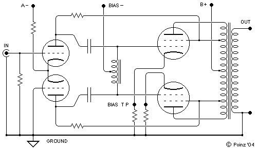
It is a means of feeding balanced NFB around a PP power stage. It is plate-to-grid for the power stage, and is dependant on the plate z of the driver valves and tapping percentage for its amount. I have a schematic drawn by Poinz illustratiing the circuit.
regards,
Douglas
|
|
|
|


