Home » Sponsored » Pi Speakers » Modifed 4 Pi Build Report (Design)
Modifed 4 Pi Build Report [message #68569] Fri, 15 July 2011 23:46 Go to next message
Dave_S is currently offline  Dave_S
Messages: 28
Registered: April 2011
Chancellor
This my build thread of modified 4 Pi speakers. I purchased the parts from Wayne and chose the B&C DE250 compression driver upgrade, the JBL 2226 woofer upgrade, the 15 gauge inductor upgrade, the Jantzen Zcaps upgrade, and the Mills resistor upgrade.

What drew me to the 4 Pi speakers was that I had only heard one pair of commercial speakers that impressed me. Those were the Klipsch Chorus II speakers. At that time, I turned of the clasical music that sounded good on most speakers to my untrained ear and put my own CD of various alternative rock music. All speakers failed to impress, except the Klipsch. Since I did not have the money at that time after college, I selected the Polk 5 Jr+ speakers. Nowadays, Klipsch are not even available to listen to in my area. Over the years, I have listened to other speakers and determined that it was not worth the money to upgrade from my Polk 5 Jr+ speakers. I was left unimpressed and had almost given up upgrading my speakers. I do not have access to stores that have high end speakers, except the Best Buy Magnolia Room that has speakers that cost up to $1000 a piece. All of those speakers sound really bad to me and left me wondering if my hearing had degraded to the point where no speaker would sound decent. While on a trip, a coworker convinced me to consider building speakers. My only experience building speakers was in college. I randomly changed out drivers from old speakers with new drivers purchased from Radioshack. I made cross overs from windings made of magnet wire. They failed to impressed and I would never have considered building my speakers myself had it not been for the coworker.

Klipsch Chorus II speakers:

index.php?t=getfile&id=545&private=0

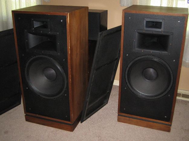
It was sort of shot in the dark, but I decided on 4 Pi speakers. To me it was a huge risk. One reason was that I decided to take the risk was that the speakers had a similar look to the Klispch speakers that I liked. I had never taken the grills of of the Klipsch speakers and the term horns meant nothing to me at the time. The Pi speakers also have more positive reviews than any other DIY speaker that I could find; the one exception might be the Linkwitz Lab Orions, but I did not have enough money burning a hole in my pocket. In many forums, Pi speakers are not mentioned and other designers are mentioned as having a good speaker design "pedigree". However, it was usually difficult to find people that had built the speakers. As for 4 Pi speakers, there were the build reports like I am doing that were all favorable. However, if you look at places like newegg.com, most all reviews of speakers that would make me cringe are positive. I placed more weight on forum posts where people were asked if they had heard the Pi speakers. There was often the reply that the person had walked by them while being demoed and they sounded really good. They were people with nothing invested in having anything but an honest oppinion.

Looking at the frequency response, my coworker was surprised by the frequency rolloff at the low end of the speaker. He concluded it was probably due to cabinet size. After some research, I determined that it was and decided to research making a larger enclosure. During the research, I saw that Wayne liked the rolloff of the 4 Pi design, because it blends with the subwoofers well. Since I may (at least initially) skip the subwoofers, I decided to make larger enclosures to extend the low frenquency response. It was a major decision because of the size. I decided on an enclosure that is about 5 cubic feet in volume. It could have been easily decreased down to 4.5 cubic feet with little negative affect, but due to other design issues, I ended up with my final enclosure size. For determining the enclosure size and frequency response, I used WinISD. I kept the enclosure tune to 38 Hz like the original 4 Pi design. The software is easy to use, but it does not shut down properly in Windows 7. I had to do a control-alt-delete to kill the program. The theoretical frenquency response of my speaker compared to the stock 4 Pi is shown below. The modified 4 Pi is the green curve:

index.php?t=getfile&id=546&private=0

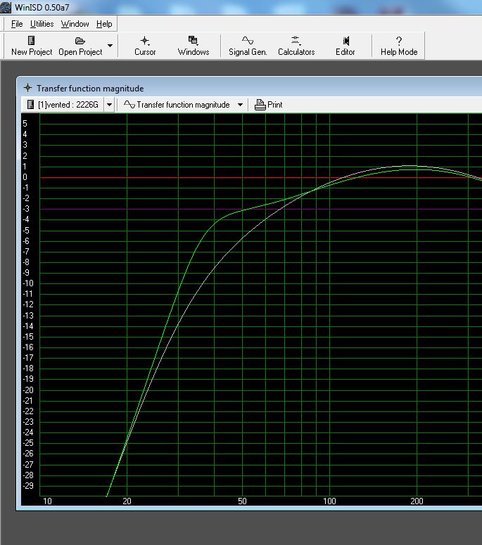
The software does not have any ability to determine standing wave issues to to the modified enclosure design. I had to take the risk. In addition, the tweeter/crossover cannot be included in the design.

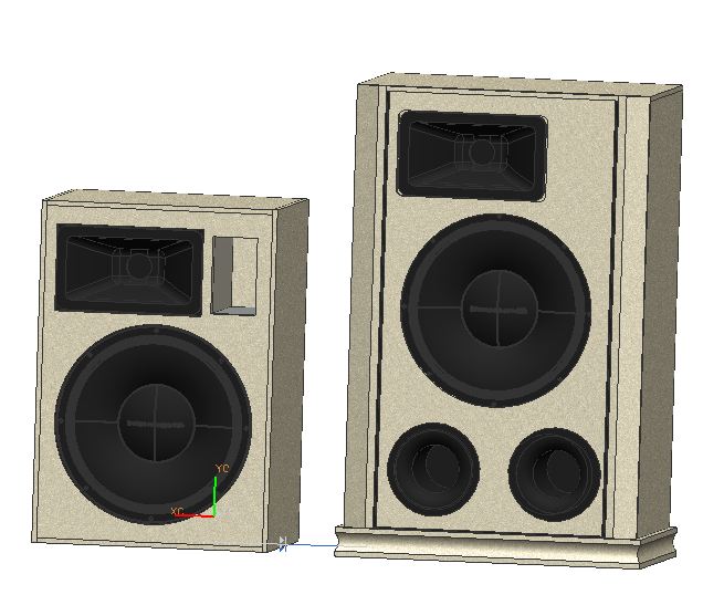
For the design, I used Unigrahics for the cabinet design. It is the software that I use most days at work. I decided on base and wood trim to protect some of the veneer edges and provided a contoured edge. This is the design that I came up with:

index.php?t=getfile&id=547&private=0
index.php?t=getfile&id=548&private=0

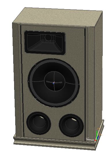
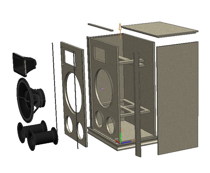
The following image is a comparison of the 4 Pi speaker to the modified 4 Pi speaker:
index.php?t=getfile&id=549&private=0
Re: Modifed 4 Pi Build Report [message #68570 is a reply to message #68569] Fri, 15 July 2011 23:56 Go to previous messageGo to next message
Dave_S is currently offline  Dave_S
Messages: 28
Registered: April 2011
Chancellor
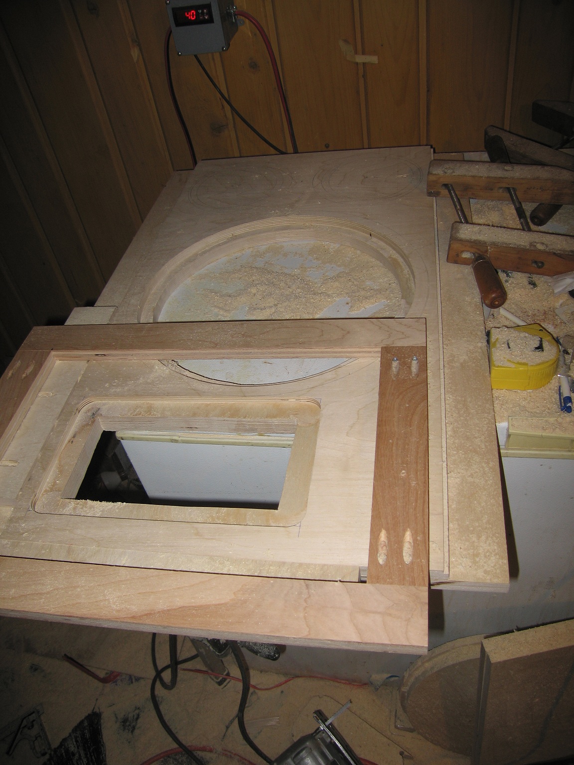
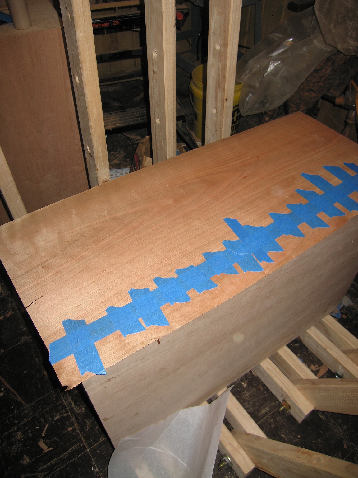
Here are a few images of the build. I chose baltic birch for the sides and a cherry veneer.

Router guide for horn:

index.php?t=getfile&id=550&private=0

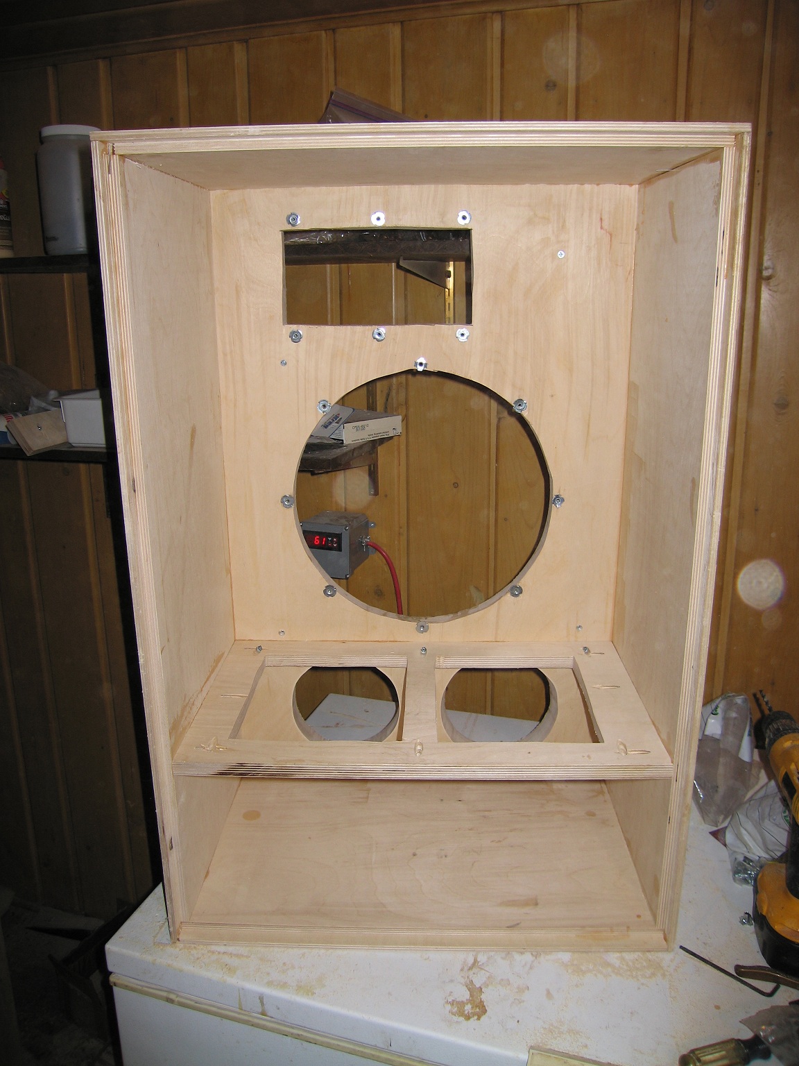
Rear open encolsure:

index.php?t=getfile&id=551&private=0

I decided to use spliced leaves of veneer and made a what was probably a bad choice of contact cement to apply the veneer. Following the glue directions closer might have helped, but I had done some veneer work years ago and had decent results. I thought that I knew what I was doing. That wasn't the case. I started on the backs of the speakers, but the results were so bad that I stripped the veneer off and decided to start over. To replace the veneer, I purchased 2-ply veneer and it worked well. There was a lot more stiffness, structure, and durability than the veneer leaves that I was using. Looking back, changing the brand of contact cement may have worked with 2-ply veneer, but I decided to make a veneer press. Some of the veneer press images are shown below:

index.php?t=getfile&id=552&private=0

index.php?t=getfile&id=553&private=0

index.php?t=getfile&id=554&private=0

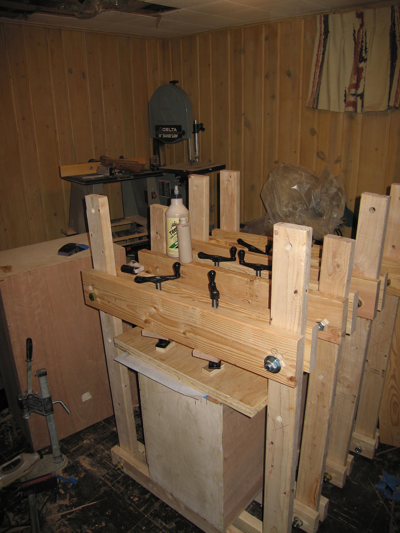
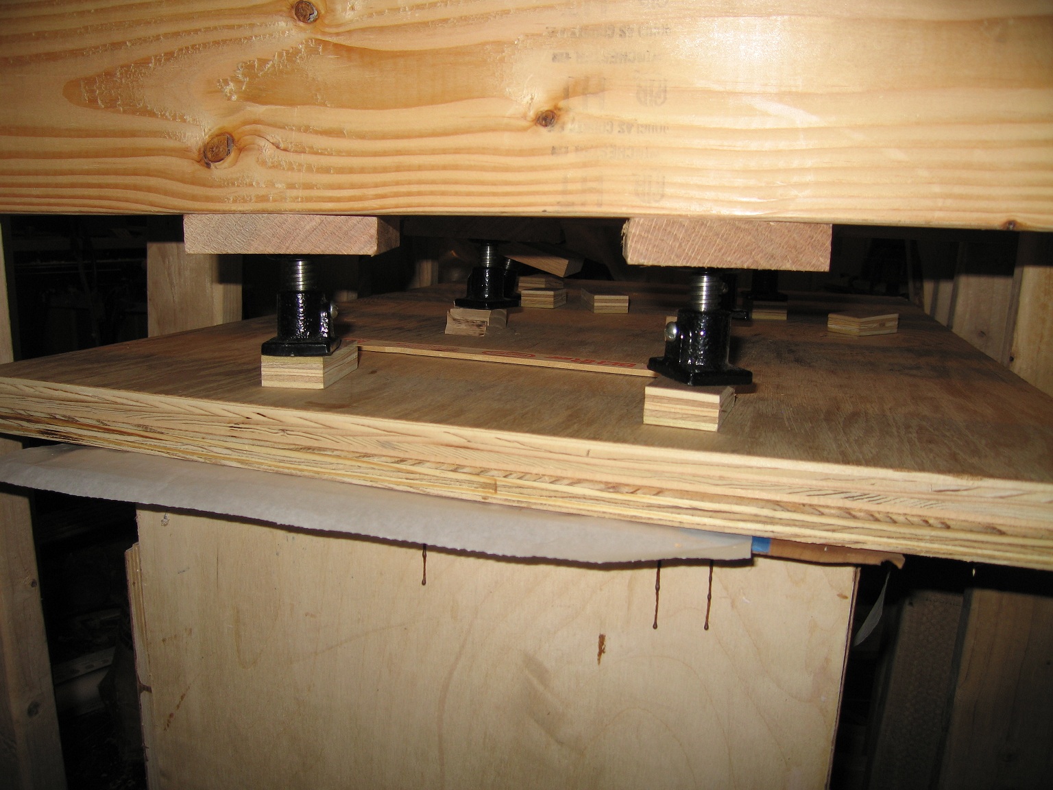
The press works fairly well. I am sure that it doesn't come neer the 100 psi recommended on the bottle, but vacuum presses can't exceed 14.7 psi, so I took the chance. In general the press worked well. In the future, I would expand my press clamps from 8 to 12. My first attempt to span about 3.5 ft with 2X4s. I used 4 press clamps on the first assembly. A 2X4 broke with force being applied by any of the clamps. I switched to 2X6 lumber on the top and increased the strength by a factor of about 2.5 times. I also used fewer clamps per assembly and shorted the span of each assembly to about 2 feet. This increased the press strength substantially. I was still never sure if anything would break but it worked well. For the platten that was used to press the veneer, I glued and nailed two sheets of plywood to make a stifff platten. For places where I rounded the corners of the cabinet with my sander, I had to go back and reclamp those area separately. I also ran into problems on the front of the speaker cabinets. The area between horn and the woofer were too flexible to generate a decent clamping force. If my internal braces were in place, it probably would have worked better. I definitely do not recommend that everyone switches from veneering to building a press. The press was expensive and still had areas where the veneer did not adheer properly. If people use a better contact cement and a more rigid veneer like 2-ply or NBL veneer, they should be fine. Also, I don't think that a veneer press would be a suitable choice for MDF due to strength and flexibility issues. Next time, I will probably take Bill Epstein's advice and try urea resin for glue.
Re: Modifed 4 Pi Build Report [message #68571 is a reply to message #68570] Sat, 16 July 2011 00:03 Go to previous messageGo to next message
Dave_S is currently offline  Dave_S
Messages: 28
Registered: April 2011
Chancellor
This is a picture of a web clamp being used on the base. There is also a press clamp shown:

index.php?t=getfile&id=555&private=0

This where I am now:

index.php?t=getfile&id=556&private=0

I am almost ready to apply finish. The speakers just need some wood filler and finish sanding. I also need to fill the void where the beveled edge meets the base. Overall, there are several defects in the veneer, but I am generally satified with the results. In my oppinion, the huge ports are a bit ugly, but I can live with them. I put a strip of walnut between the cherry veneer and the solid cherry. It may have been better with with more contrasting woods like walnut and maple, but I decided to see what happened. Cherry will darken with time, so the contrast between walnut and cherry will likely fade with time. I really like the cove molding on the base. I was done by creating a table saw fence that ran at about a 20 degree angle to the saw blade. There may be sound issues from the cavity beneath the speaker, but I will deal with it.


Future posts:

-Finished speaker
-Sound testing I borrowed a high quality microphone from work. I plan to test at least for frequency response. If the room response testing works, I will report on that also. I plan to use Arta Software for the testing.
Re: Modifed 4 Pi Build Report [message #68573 is a reply to message #68571] Sat, 16 July 2011 08:55 Go to previous messageGo to next message
Wayne Parham is currently offline  Wayne Parham
Messages: 18677
Registered: January 2001
Illuminati (33rd Degree)

Lookin' good? Do you have any measurement software to check for response blips from standing waves?

Re: Modifed 4 Pi Build Report [message #68575 is a reply to message #68573] Sat, 16 July 2011 12:12 Go to previous messageGo to next message
Dave_S is currently offline  Dave_S
Messages: 28
Registered: April 2011
Chancellor
Quote:
Lookin' good? Do you have any measurement software to check for response blips from standing waves?


Thanks. I am not sure. What software feature should I look for? This is all a completely new to me. Also, is there a frequency range that the standing waves occur in?
The testing will likely be for my own learning, but it would not be beyond me to tear them all apart in 6 months and build a new cabinet if I could improve things. Hopefully, testing does not point out some audio defect that I begins to irritate me.

I did some testing by ear before veneering to at least see if there were any sound quality defects that would drive me nuts. I did not hear any. My plan was to perform a gated frequency response and possiby a cumulative spectral decay analysis. The cumulative spectral decay analysis (the waterfall display) should be more for room modes if I understand things correctly. My guess is that standing wave issues would be visible as dips or peaks in the gated frequency response plot.
Re: Modifed 4 Pi Build Report [message #68577 is a reply to message #68575] Sat, 16 July 2011 15:37 Go to previous messageGo to next message
Wayne Parham is currently offline  Wayne Parham
Messages: 18677
Registered: January 2001
Illuminati (33rd Degree)

Look for response blips in the midbass to midrange, from about 60Hz to 300Hz or so. Above that the insulation will work. You will want to use something that can measure amplitude response, although you can see evidence of the standing waves in an impedance sweep. That's a simpler measurement, however, it won't tell you how severe the peaks might be.

One thing that will help is to use a sheet or two of insulation spanning the cross-section of the cabinet, splitting the top and bottom of the cabinet (and maybe even in more than one dimension) in addition to the insulation that lines the walls.

Re: Modifed 4 Pi Build Report [message #68578 is a reply to message #68577] Sat, 16 July 2011 18:48 Go to previous messageGo to next message
Dave_S is currently offline  Dave_S
Messages: 28
Registered: April 2011
Chancellor
Thanks. It looks like I have the ability to measure impedance. If I can understand what to do and obtain the proper parts, I will give impedance measuring a shot.

There is insulation over about 75% of the cross section. If more is needed, it can be added.
Re: Modifed 4 Pi Build Report [message #68598 is a reply to message #68578] Sun, 17 July 2011 17:46 Go to previous messageGo to next message
Nichol1997 is currently offline  Nichol1997
Messages: 21
Registered: December 2009
Location: Virginia
Chancellor
Hmm...your build looks vaguely familiar...
http://audioroundtable.com/forum/index.php?t=msg&goto=61737
Re: Modifed 4 Pi Build Report [message #68602 is a reply to message #68598] Sun, 17 July 2011 20:09 Go to previous messageGo to next message
Dave_S is currently offline  Dave_S
Messages: 28
Registered: April 2011
Chancellor
Quote:
Hmm...your build looks vaguely familiar...
http://audioroundtable.com/forum/index.php?t=msg&goto=61737


Your design is probably where I started. Thanks. I didn't realize that the final speakers were so similar since my design went through so many iterations. I took your window design for the internal brace. Your post also directed me to WinISD. With the speakers, about the only choice is to have dual ports. I really wanted to use two square ports like the original 4 Pi, but Wayne's feedback on your idea for a long thin port talked me out of that. The two rectangular ports rotated 90 degrees to the original orientation would have been similar enough to a long thin slot. Your ports are more streamlined than mine. I went with flared ports and the flares make their diameter substantially larger -- almost obnoxious. The flares are supposed to reduce whistling from air movement, but I have a hard time believing that I will ever hit the volume level where that would be an issue. I missed Wayne's suggestion in your post of measuring impedence to detect standing waves. It is something that I will have to look into.

I also used the following link for the beveled edges and darker wood strip: DTWQT speakers. That design feature is probably better for small drivers, since my speakers ended up being 23 inches wide. The width also preserved the golden ratio better for speaker dimensions. The golden ratio (internal length/width/height ratios of .61 x 1 x 1.61) is supposed to reduce standing wave issues. It is probably a silly ratio and the importance is often discounted nowadays, but I didn't want to find out that I was wrong. I winced when I held a tape measure up to where I was placing them during the design. It is amazing what a few extra inches will do to the size of the speakers.

I don't remember where I took the base design from. It was a originally a simple slab at one time like other speakers, but I decided to go with the cove molding to raise the horn elevation by a few more inches after my initial sound testing. In addition, I was trying to give the speakers more of a furniture look. I like having a base so that I can slide the speaker around without worry.

Did your friend with Klipsch speakers ever listen to your speakers and offer an opinion? My biased comparison with 18 years of cloudy memory in between is that the 4 Pi speakers have a similar sound, but use better drivers that can generate more accurate sound reproduction. I have not heard my final speakers with all braces and acoustic insulation in place yet.

Re: Modifed 4 Pi Build Report [message #68630 is a reply to message #68602] Mon, 18 July 2011 20:57 Go to previous messageGo to previous message
Nichol1997 is currently offline  Nichol1997
Messages: 21
Registered: December 2009
Location: Virginia
Chancellor
My ports don't suffer from any kind of whistling noises, even when driven hard with bass heavy songs at full tilt. I am sure you won't have a problem either.

My friend with the Klipsch speakers did like the Pi4s. He thought they sounded really good but did not say if he liked them more than his Klipsch speakers.

What is the internal dimensions of your speakers?

Previous Topic: Setting 4pi LCR upside down in theater?
Next Topic: Looking for a few extra watts for your Pis?
Goto Forum:


Current Time: Thu Apr 25 03:20:50 CDT 2024

Sponsoring Organizations

DIY Audio Projects
DIY Audio Projects
OddWatt Audio
OddWatt Audio
Pi Speakers
Pi Speakers
Prosound Shootout
Prosound Shootout
Smith & Larson Audio
Tubes For Amps
TubesForAmps.com

Lone Star Audiofest