|
Home » Audio » Speaker » Help me make the leap (I bought my drivers. Now I need help pulling it all together.)
|
|
|
|
|
|
| Re: Help me make the leap [message #61928 is a reply to message #61926] |
Mon, 22 February 2010 19:48  |
 |
 Wayne Parham
Messages: 18674
Registered: January 2001
|
Illuminati (33rd Degree) |
|
|
| NEO Dan wrote on Mon, 22 February 2010 17:16 | In my situation I will be crossing over much lower than the point at which the woofers directivity starts to narrow as I want to keep as much of the imaging cues coming from the point source as possible.
|
Knowing that you want the imaging cues coming from a point source (as I do), why not use a point source for the midrange as well as the treble? I realize these comments are made in the array forum, but your comments beg the question.
| NEO Dan wrote on Mon, 22 February 2010 17:16 | Knowing that only the WG will be approaching it's usable pattern cutoff, do you have any tips for getting things to come together properly. Is this situation a severe hurdle to good performance?
|
There are some deal-breakers where horns/waveguides are concerned. One is you don't want to send a signal to the driver below the point where excursion rises rapidly. That's a recipe for increased distortion and possibly driver failure. A deal breaker, if you asked me. Another problem is, if the horn is designed for constant directivity, you don't want to use the horn below the point where it loses directional control. That's a deal breaker too. Might as well not use a CD horn, if you're going to push it below the point where it's not CD anymore.
Sometimes a horn really only has control in one plane (usually the horizontal) at the bottom of its passband, and vertical control comes in (hopefully smoothly) within the first octave or so. That's workable, particularly since driver-to-driver interactions set the vertical pattern anyway. But what isn't a good idea, in my opinion, is to use a horn designed for constant directivity below the frequency where it is able to set the pattern in the horizontal plane.
At high frequency, the horn sets the pattern and the acoustic load is primarily resistive. These are the benefits of horn loading. At low frequency, the horn is acoustically invisible. It's like it isn't even there. And since the driver is designed with an assumption that it will be presented an acoustic load that limits its excursion, it is ill-equipped to handle low-frequency content. Distortion rises and the excessive excursion may cause damage, sending the diaphragm into the phase plug. One can always derate the device, allowing only low-power, and that may prevent damage but I still question the wisdom of using a horn at too low a frequency. It isn't providing any benefit.
Then there is a transition region, where the horn begins to provide acoustic loading and directivity control. The trouble is, this sometimes isn't a smooth transition. It is a range where the acoustic loading often swings largely from reactive to resistive, which in turn causes rapid phase movement that is hard to design (the crossover) around.
The take away from all this for me is, unless there are compelling reasons why I need to run a horn lower than it is really designed for, I usually don't.
| NEO Dan wrote on Mon, 22 February 2010 17:16 |
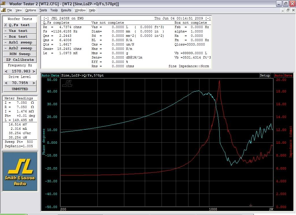
I know the WG+CD combo has a lower impedance peak at 1,126hz.
|
This is probably the first quarter-wave mode (resonance), and it generally marks the beginning of the transition region. Sometimes, you can use a horn right down to that frequency with good results, at least as far as acoustic loading (and crossover phase) are concerned. It may not be able to control directivity very effectively yet at that low frequency though, and in this case, there will be evident some response steps and/or ripples at frequencies where directivity changes, where it goes from a wide (uncontrolled) pattern to a more narrow beam set by the horn.
Honestly, your impedance chart looks pretty good, and I think this horn/driver combination will be very well behaved from 1.2kHz up. I often see two quarter-wave mode resonances, sometimes three, towards the lower end of the range, and there are sometimes diaphragm breakup resonances up high. I'm guessing the horn probably has pretty good pattern control; At least horizontal control down to the quarter-wave mode and it probably gains vertical control in the next octave or so. If so, that's pretty good, as good as it gets, really. I think if you crossover anywhere in the 1kHz to 2kHz range - wherever directivity matches and the forward lobe is positioned properly - it will sound nice and give a good, uniform pattern.
The thing is, getting back to the point source, the use of a controlled directivity tweeter, and matching to the midwoofer or midwoofers, I think the whole point of using a CD horn / waveguide is uniform directivity. That's why we use them. If that isn't the goal or at least one of them, there probably is little reason to use a CD horn. You could use a different kind of horn; It becomes almost arbitrary.
One possibility that occurs to me is to configure the array so that it comes online in stages. Maybe allow only the midwoofer driver(s) nearest the waveguide to run all the way up to match the tweeter, and crossover where their directivities match.
This could be done in the form of an MTM configuration, perhaps. The main thing is, the tweeter horn and midwoofer(s) should be crossed over roughly where horizontal directivity matches, within about an octave. You have some wiggle room there, but don't go too far or the horizontal pattern suffers. At the same time, the C-T-C spacing should be such that the vertical nulls are about where the tweeter pattern falls off at HF. These are the two things to balance.
Then maybe you could bring in the rest of the midwoofers a little lower, in the range where they sum well. I guess this would be a sort of staged transition from array to point source, something I think you'd have to work out if you were going to try and mate an array with a waveguide.
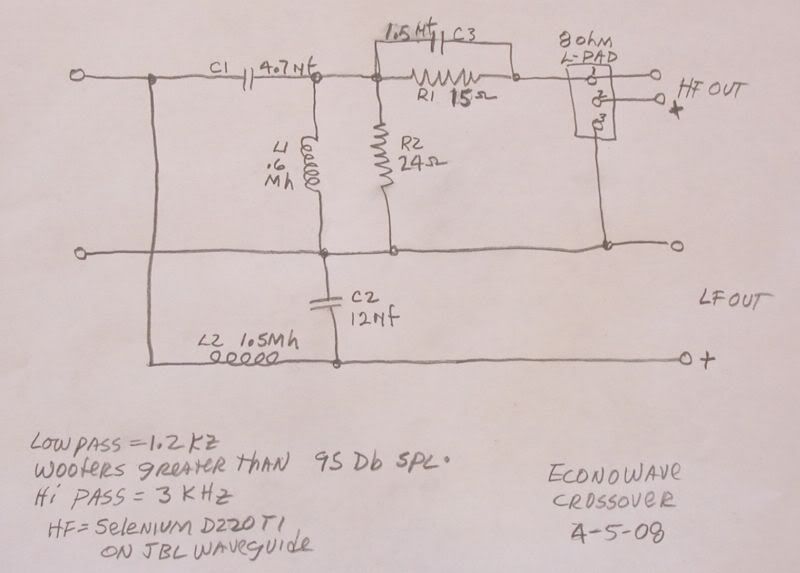
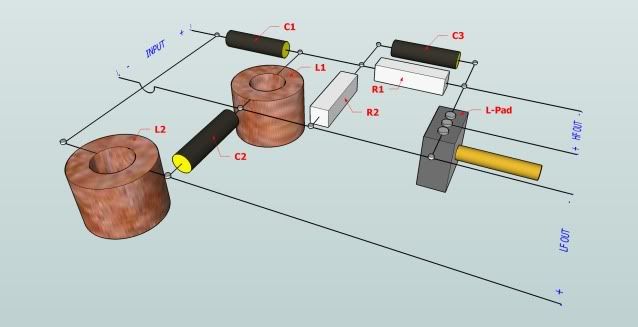
One link I failed to provide in my last reply was my crossover document. It shows a lot of configurations that may be useful for you, from first-order to third-order, all with CD compensation for the top-octave. I used Spice to model the circuits, and the schematics and transfer functions are shown. I've also found a few more posts in the archives that may shed some light on the matter for you. My approach may not directly relate to your array, as they are very different things. But as for crossover circuits, CD horn / waveguides and matching directivity, these links will probably be useful for you. At the very least, they'll give you a baseline, something known to work, and provide some food for thought.
|
|
|
|
Goto Forum:
Current Time: Tue Apr 16 11:18:05 CDT 2024
|


 Posting Rules
 Members
 Search
 Help
Help Register
 Login
Login Get a T-Shirt!


 so I kind of gave up on that for the moment.
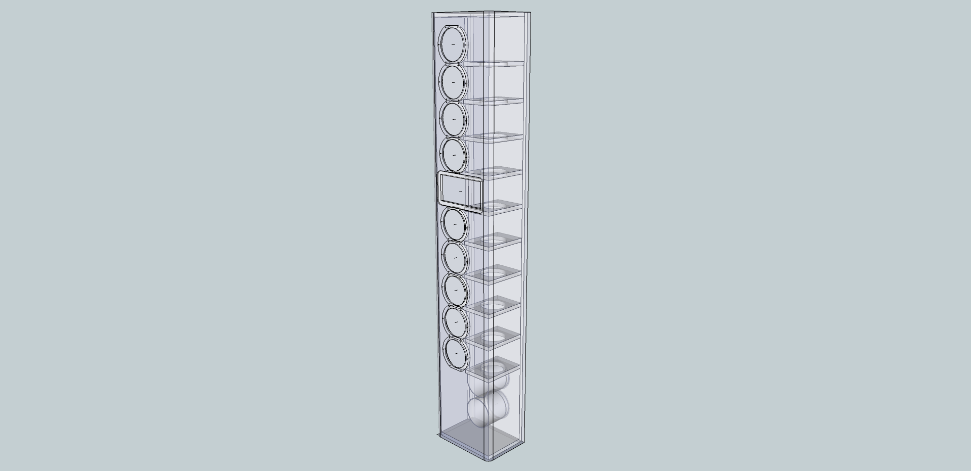


")

