
Posted by Wayne Parham [ 70.234.97.75 ] on February 28, 2008 at 18:22:18:
In Reply to: PCB Crossovers posted by Jshoc on February 04, 2008 at 11:22:52:
You betcha. We have plenty of them in stock.
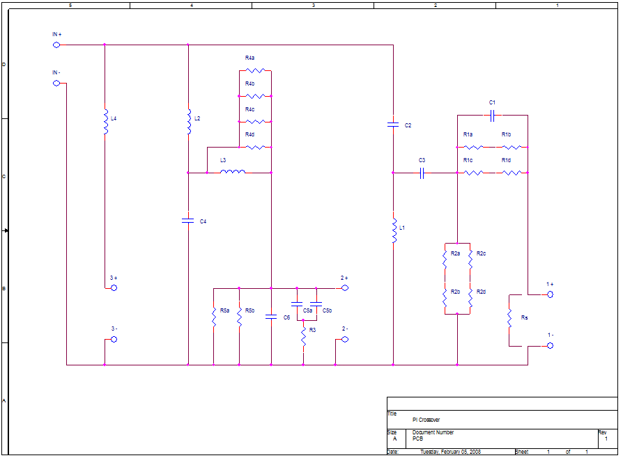
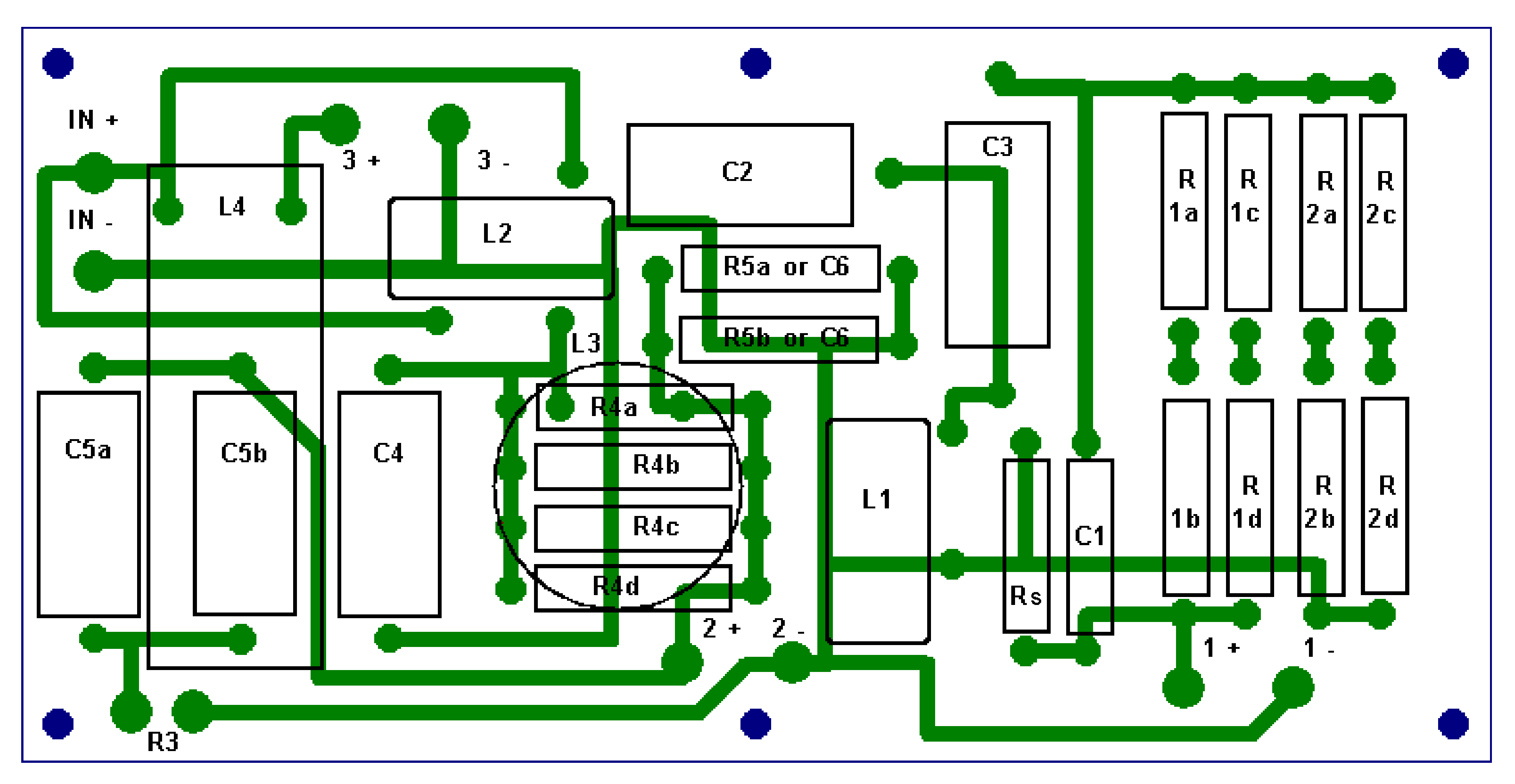
I basically made this board capable of supporting my whole line of speakers (except one π and two π) without having to resort to putting components in cable assemblies. There is ample room to mount every component for each of the models. The only exception is the Zobel resistor R3 is mounted off-board. It has mounting holes and is designed for chassis mount, so you wouldn't want to mount it on the circuit board. It is connected to the PCB with spade lugs instead. In some cases component locations are shared in the midrange/midwoofer circuit, where two models have two different configurations. But there is plenty of room for everything, and it is easy to lay it all out with the traces and lands provided.
[ PiSpeakers Forum ] [ Help ]