|
Home » Sponsored » Pi Speakers » Finished Pi 4 with photos
|
|
| Re: Finished Pi 4 with photos [message #59511 is a reply to message #59503] |
Wed, 24 June 2009 11:46   |
 |
 Wayne Parham
Messages: 18677
Registered: January 2001
|
Illuminati (33rd Degree) |
|
|
Excellent, interesting project.
I like the implementation. That's the horn some of the folks at AK use in their "Econowaves". I would probably have used that horn if I were looking. From the measurements, I'd say it was basically equivalent to the horns I use.
When I see Econowaves built with 12" or 15" drivers, I think of them as three π or four π derivatives. They're the same basic speaker. Same crossover, same design approach. So I definitely give the thumbs up.
The only thing that concerns me is what you mentioned about the position of the lobes and nulls. That is affected by crossover phase (set by crossover values and topology), acoustic phase (set by electro-mechanico-acoustic rolloff of drivers), directivity (set by horn flare and/or size of direct radiators) and position of the drivers on the baffle (vertical, horizontal and depth/distance). This means that the changes you have made most likely moved the positions of the lobes and nulls, and while you can guestimate them by looking, you can't know for sure without measurements.
The horizontal performance is set by the size of the woofer, the pattern of the horn and the crossover frequency. Since the size of the woofer and the directivity of the tweeter are constants, the only thing you need to set is the crossover frequency.
Your horn provides uniform directivity of 90° above about 1kHz. The woofer directivity collapses to 90° around 1kHz too, since this occurs approximately where radiator diameter=λ. Remember of course, radiator diameter isn't advertised diameter, it is approximately where the surround meets the cone, maybe half way into the surround or so. This is what sets the crossover point, because you want to match the horizontal directivity of the horn to the woofer's pattern at crossover. By doing this, you avoid response ripple at wide off-axis angles, ensuring uniform power response and spectral balance throughout the room.
You actually have a fair amount of wiggle room where horizontals are concerned because movement along the horizontal doesn't change the delta distance between the woofer and the tweeter. You can put the crossover band anywhere within about an octave of the diameter=λ point, which is where directivity is approximately 90°. The horizontal lobes are fairly far apart, and aren't due to woofer/tweeter interaction like the verticals are, they're due to path length distances across the woofer, itself.
The verticals aren't so easy. This is where crossover phase and baffle spacing are most important. When I was first designing loudspeakers, I didn't have good measurement equipment so my calculations were probably better than my measurements. What I had at my disposal were Radio Shack SPL meters, microphones and oscilloscopes. I found early on, in the 1970's and 1980's, that I really had little visibility, so I tried to calculate everything. It was very tedious math, and even though I was dilligent, I couldn't get the accuracy I have now from a PC measurement system.
In the past, I would spend all day calculating a series of phase angles at various frequencies and positions, calcualting first the crossover phase and then relating that to physical distances to find the lines where I expected the null angles to be. This was all outlined in the original first couple of drafts of my "Speaker Crossover" document, but I later took those pages out, the ones dealing with phase angles and manual calculations. It was long, tedius and boring, and these days, just doesn't make sense anymore. Take the time you'd spend to calculate one set of vectors, use that same time to work your regular day job and apply the money towards a good measurement system. 
It's absolutely trivially easy, in comparison, to take measurements at various points in front of the loudspeaker, to find where the nulls are. Of course, you have to be in the ballpark to start with, but there's a wealth of information here, on this website, to help find a good starting point. I see you chose to use the four π crossover to start with - that's good, it's definitely going to get you close and may not need to be changed at all.
You may find that you have to move the horn forward or backward a bit, to fine tune the position of the forward lobe. Or if you want the horn to be baffle mounted (as I see you do), then you might choose instead to modify crossover values a little bit, if needed to fine tune the position of the forward lobe and vertical nulls.
Sometimes just slightly modifying the value of a crossover component or two will do it, other times you will have to modify the slope of the core splitter filter (by adding or removing a reactive component). Even orders tend to form symmetrical lobes, but electro-mechanico-acoustic rolloff adds to the acoustic slope, so you may end up with odd orders electrically. Or you may have an asymmetrical filter, with different slopes on the drivers. More than likely, you'll have what appears to be a different crossover points for each driver, by textbook values, because acoustic summing comes into play.
My advise is to spend an afternoon or two measuring your speakers. Lay one of them on its back and use a boom to position the microphone over it. Take a measurement with the mic in one position and then move it to take another. Do this enough times you have a grid of measurements to see what the loudspeaker's pattern looks like. If its response is clean through a wide forward lobe of 40° or so (20° or more up and 20° or more down) then you're doing fine. That vertical arc is tall enough to be useful, and will ensure that the speaker sounds good at various heights at virtually all listening distances in your room, even fairly close up. If the pattern isn't right - if a null is too close to the forward axis - modify the crossover and take measurements again. Repeat this process until you are satisfied with your speaker's performance.
|
|
|
|
| Re: Finished Pi 4 with photos [message #59515 is a reply to message #59503] |
Wed, 24 June 2009 19:17 |
Psychoacoustic
Messages: 75
Registered: May 2009
|
Viscount |
|
|
Wayne, appreciate the time for such an informative reply. Have completed a couple of Econowave projects and it was your posts on that thread which brought me to Pi speakers.
Subjective impressions and arbitrary opinions won't help much to make decisions about a speaker's performance- that much I understand. But I know for certain that I was really pleased with all aspects of the this project's 'trial' version, with horn just sitting of top of the cab driven by the Pi 4 crossover. Although I've not spent a great deal of time auditioning the finished project, I don't have that previous confidence about it.
Regarding measurement- I appreciate your advice, and know this is the only reliable method. Purchasing measurement equipment, a laptop computer and learning to use the gear and interpret/apply results is a journey I'm not ready to begin just yet. I was hoping to avoid that by building a tried and proven design. Dammit! Shouldn't have messed with a working formula!
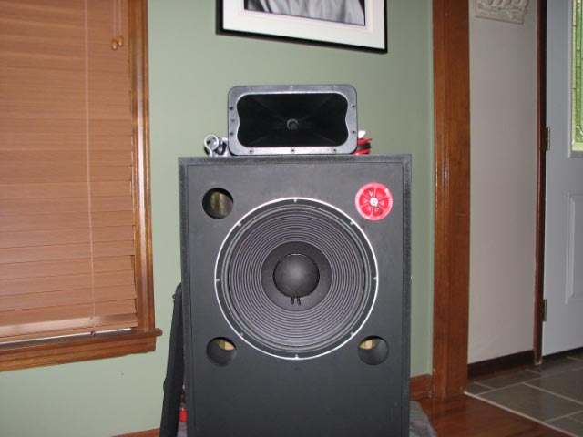
Aside from the cabinet volume (5cu ft) there are two differences between the original Pi 4 and the derivative I posted. They concern, as you described, the spacing of the vertical nulls, i.e. tweeter to woofer distance and distance to listener. Looking at the Pi 4 baffle cutout plans, the distance from top of woofer cutout to bottom of waveguide cutout is approximately 1.5"- is that correct? In the speakers I made that distance is approx 1/2", though comparing photos of Pi 4 from your site and those above, they look quite similar. Can (e.g.) half an inch make an audible difference? The other difference is that the flush-mounted waveguide is 15mm forward (of the woofer). If necessary, it wouldn't be too hard to alter the finished speakers to exactly replicate those distance measurement aspects of the Pi 4 design.
Also, the additional 15mm baffle layer has extended the total port length by 6cm. To return ports to original length (40Hz tuning), would I need to cut 15mm off of the end of each of the four ports or could I cut 60mm from the end of one port? I'm guessing that the additional port length has changed the voicing of the speakers somewhat.
So what I'm thinking of doing is firstly returning the speakers to their previous 'trial' state and reassessing. It's easily done and reversible; waveguide and driver back on top of inverted cabinet and cut a cover plate to seal the waveguide cutout in the baffle.
|
|
|
|
| Re: Finished Pi 4 with photos [message #59516 is a reply to message #59515] |
Wed, 24 June 2009 20:04 |
|
Wayne Parham
Messages: 18677
Registered: January 2001
|
Illuminati (33rd Degree) |
|
|
As I said earlier (or tried to say, but may have been too wordy) the basic setup looks very close to me, so I would expect results to be good. I would further expect you'll be in the ballpark with respect to the position of the forward lobe and nulls. The thing is, even though the horns look similar in appearance, size, basic shape and polar response - they're not the same, so there is some question how their subtle differences might change things, specifically in the critical crossover region.
The lower end of the passband is where crossover is done, and that's where a horn or waveguide is most compromised. The differences between similar horns/waveguides are manifested mostly in this region. Directivity and acoustic phase are shifting in the lower end of the passband, and those things contribute pretty heavily to the on and off-axis summing between adjacent subsystems.Basically what I'm saying is it could be a drop-in replacement, or it could be some small changes are in order.
|
|
|
|
|
|
|
|
| (Now they're REALLY) Finished Pi 4 with photos [message #59584 is a reply to message #59503] |
Wed, 01 July 2009 18:44 |
Psychoacoustic
Messages: 75
Registered: May 2009
|
Viscount |
|
|
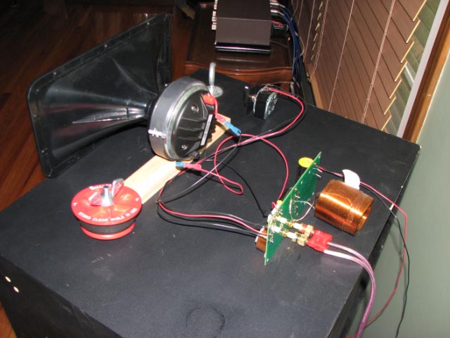
One of my Dad's favourites was "If it ain't broke, don't fix it". Too true. The JBL waveguide on DE250, in general, sounded very good. But after having identified and rectified the anomaly that was nagging at me, (vocals were too pronounced, or 'shouty') and rectifing this problem, I wouldn't say that it was an automatic alternative for the H290 without modifications to the standard crossover. It was an interesting, educational experience which I presume demonstrated the concern that was raised about the '... position of the forward lobe and null(points)'. Comparing the dimensions of the JBL and Eminence H290 horns, there appears to be a significant difference in length (throat to front edge).
On the first audition, it was clear that the sonic difference between the horns was not subtle. The H290 was smooth, balanced and very easy to listen to at all volume levels. Detail and imaging were really outstanding- three dimensional. Anecdotally, listening to a fairly lackluster pressing of the Beatles 1968-1970 (blue album) revealed subtle nuances for the first time and breathed new life into the album.
Still have some postion experimentation to do regarding tilt and height. Will consider trying some rigid fibreglass sound absorption on the ceiling just forward of the speakers.
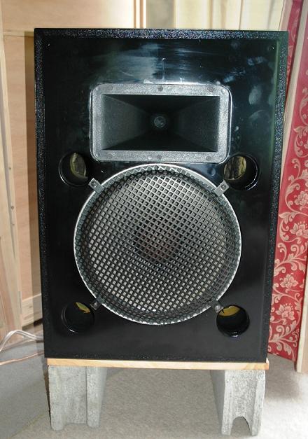
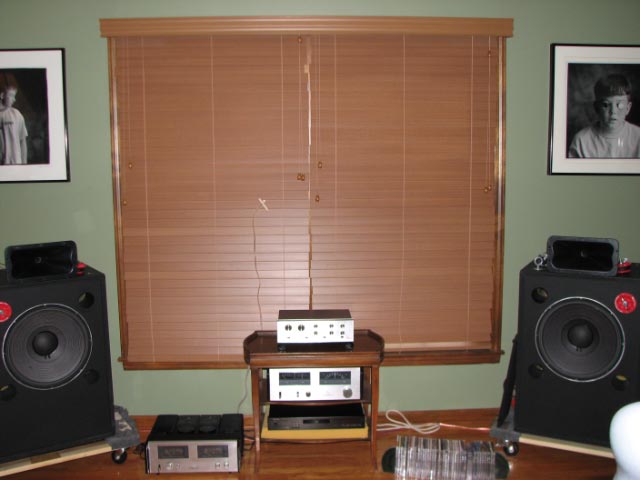
Below is a photo of the (grubby) project with H290 fitted.
|
|
|
|
|
|
| Re: (Now they're REALLY) Finished Pi 4 with photos [message #60378 is a reply to message #59587] |
Fri, 10 July 2009 12:20 |
Russellc
Messages: 397
Registered: May 2009
|
Illuminati (1st Degree) |
|
|
I know this message is getting a little old, but I remember you I believe from the Econowave thread. I have a very similar project,
the same JBL 4507 cabs, I did have JBL 2225H in there which is very similar to the 2226H, but have changed to the 2235H driver, and thats why you see one port plugged. I'm not sure I understood one of your posts, Ihope you didnt alter the length of the tubes inside the 4507 cab. I would restore that if so. The cab can be easily tuned differently by plugging various ports with plumber's test plugs ( 3 inch). All 4 open is 40 hz, one closed is 34 hz or so. This is the same tuning, box volume as the JBL 4430 monitor, one of the reasons I installed the JBL 2235H as it is the same driver thats in the 4430 as well. with 2 ports closed you are right on about 30 hz, and the response is fairly flat. I sometimes use this tuning with thw 2235H driver as well, just a little tighter. With 3 closed, you're at the same tuning, box volume, ( and same driver if using the 2235H ) as the JBL B 380 subwoofer, I think that was 22-25 hz, cant remember now.
Likely your largest difference from the 4PI is something you mentioned in one of your last posts, The difference in length between the H290 and driver ( JBL in the pic) compared to the JBL wave guide and pictured, the Selenium driver. The compression driver shown on the 4507 boxes is the B&C DE 250.
JBL tackled a similar problem with the 4430 monitor by putting a one inch spacer on the faceplate behind the 2433 horn, which moved it forward one inch in relation to the front of the woofer.
Others, like Altec with the A7, made up for the problem by reversing the phase of the HF horn, bringing it closer in phase.
The other difference, is the crossover. They are similar, especially the compensation, but the rest is different, and the 4PI was worked to work on those parts, the JBL wave guide has the E'wave crossover worked out for it. Both would be close for the other, but they arent tweaked as well as their intended application. I also ran into questions, as I also have the H290 and various compression driver, and I tried them in various combinations with the E'wave crossover. Remeber, the E'wave project is just a high freqency unit, waveguide+ compression driver and crossover with compensation. The Low frequency is just a standard 2nd order crossover at 1600 hz or so. It is to be adjusted to your particular choice of woofer. I found with both the 2225H and the 2235H that this standard circuit sounded "OK" but wasnt quite right by a long way. Since I was using the same box size, box tuning and woofer as the JBL 4430 it was suggested to me to use the bass portion of this crossover. I built it as well as the same zobel circuit, combining that with the standard E'wave filter and compensation. Looking at the several projects some members did who have advanced measuring facility produced nice LF circuit foor their particular woofers. Many used the JBL LE 14 A 14 inch woofer, and I noticed the crossover point was pulled down to 900 hz from the standard 1600. The JBL 4430 is said to cross around 1,000, so I figured this would work, and work it has. Doesnt sound bad with the H290 either, oddly and despite the length differences, they seem to both sound fine. One combination I tried on a lark was putting an Altec 802 8G on the H290. A very enjoyable combination! Vintage Altec sound and rock solid imaging from the semi constant directivity supplied by a modern horn/waveguide! Glad to see you got it to sound the way you wanted, lots of lessons along the way.
A question concerning your mounting the horn/waveguide in the face plate of the 4507, you have it very close to the woofer which can be a good thing, but it seems like I remember a brace about there going from front to back? Its been a while since I looked inside my boxes, my HF in still perched on top.
Russellc
-
 Attachment: IMG_2140.jpg
(Size: 42.62KB, Downloaded 16550 times)
-
Attachment: IMG_2141.jpg
(Size: 42.47KB, Downloaded 16627 times)
-
Attachment: IMG_2142.jpg
(Size: 53.80KB, Downloaded 16563 times)
|
|
|
|
|
|
Goto Forum:
Current Time: Tue Apr 23 03:00:24 CDT 2024
|


 Posting Rules
 Members
 Search
 Help
Help Register
 Login
Login Get a T-Shirt!


")

