Home » Sponsored » Pi Speakers » Compensation networks - Photos
Compensation networks - Photos [message #34875] Thu, 24 January 2002 17:53 Go to next message
Wayne Parham is currently offline  Wayne Parham
Messages: 18706
Registered: January 2001
Illuminati (33rd Degree)
Here are some photos of the compensation networks used in speakers I've built. It shows how I make the cable assemblies for both the woofer and for the tweeter.


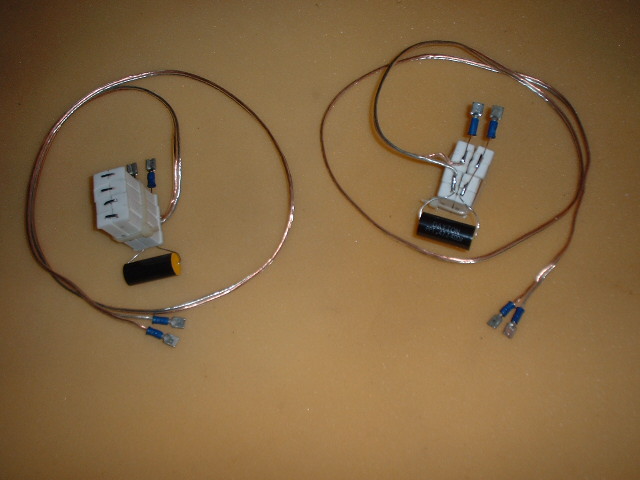
Tweeter cable assembly, including compensation components R1, R2 and C1

The tweeter compensation components R1 and R2 are soldered together and physically arranged in a "block" which is then wire tied together. The capacitor C1, spade lugs and a couple feet of interconnect wire are then soldered to the resistor block to complete the tweeter cable assembly.


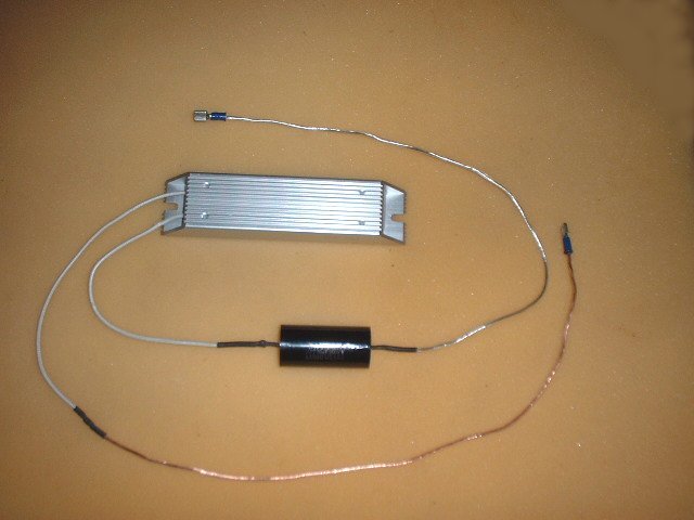
Woofer damper cable assembly, including compensation components R3 and C5

There are two woofer connections for those that include an RC damper (Zobel), and only one for those that do not (Pseudo Butterworth). In either case, the crossover PCB connects to the woofer using a straight interconnect with spade lugs on each end. There is no point in making a photo of a simple cable. But for those containing a Zobel, there is an additional connection to the RC damper cable assembly.

Resistor R3 of the woofer damper is mounted to the cabinet floor, just as the crossover PCB is. Capacitor C5 is laid on top of the fiberglass insulation where it cannot vibrate against any hard surface. Similarly, the resistors that form R1 and R2 (and capacitor C1) are laid over on the fiberglass insulation so that they cannot vibrate against the baffle or run against the crossover circuit board. The resistor block is actually supported by the rigid leads of the components soldered into the spade lugs, but this is a flexible support and the cable assembly will touch the fiberglass insulation which helps keep the heavy resistor block suspended away from the cabinet and crossover PCB.

Re: Compensation networks - Photos [message #34876 is a reply to message #34875] Thu, 24 January 2002 18:11 Go to previous messageGo to next message
replay is currently offline  replay
Messages: 284
Registered: May 2009
Grand Master
thanks wayne, can you send a set to rudi? maybe that's his problem:)

cheers,

george

Re: Compensation networks - Photos [message #34877 is a reply to message #34875] Thu, 24 January 2002 18:55 Go to previous messageGo to next message
Adam is currently offline  Adam
Messages: 419
Registered: May 2009
Illuminati (1st Degree)
Looks very clean Wayne, but wouldn't having the resistors in such blocks cause heat problems? Just curious.

Adam

Re: Compensation networks - Photos [message #34878 is a reply to message #34877] Fri, 25 January 2002 04:34 Go to previous messageGo to next message
Wayne Parham is currently offline  Wayne Parham
Messages: 18706
Registered: January 2001
Illuminati (33rd Degree)
They won't dissipate as much as if they were positioned in such a way as to allow air to flow freely around them. But we aren't skimping on the quantity or dissipation rating of the components used, and so we don't need to promote more efficient air cooling around them.

The only other solution I would have been happy with is to use two large 100 watt blocks like what is used in the woofer compensation network. If this style tweeter cable assembly hadn't proven to be a good solution, using a pair of 100 watt parts might have been an option. But it is difficult to find a variety of resistance values in such large power components and forming two 40 watt parts for R1 and R2 using 10 watt parts allows more flexibility in component resistance values. Mounting them as I have done makes the cable assembly less cumbersome to work with and I find it to be a good solution.

What I wished for, thanks, Wayne [message #34883 is a reply to message #34875] Fri, 25 January 2002 12:28 Go to previous message
BillEpstein is currently offline  BillEpstein
Messages: 886
Registered: May 2009
Illuminati (2nd Degree)
I now know that I actually configured my networks correctly! From word pictures of resistors on the beach! Caramba!
Previous Topic: piezo buzzing when amp clips.
Next Topic: Any opinions on the components from JBLs 3677s
Goto Forum:


Current Time: Tue Jun 11 22:49:26 CDT 2024

Sponsoring Organizations

DIY Audio Projects
DIY Audio Projects
OddWatt Audio
OddWatt Audio
Pi Speakers
Pi Speakers
Prosound Shootout
Prosound Shootout
Smith & Larson Audio
Tubes For Amps
TubesForAmps.com

Lone Star Audiofest